Section 04 ENGINE (2-STROKE)
Subsection 04 (TOP END)
Remove cylinder head no. 2.
If shells, sand, salt water or any other particles
are present in cylinder cooling jacket, clean with
a vacuum cleaner.
947 DI Engines
Disconnect hose of RAVE valves. Remove air/fuel
rail. Refer to ENGINE MANAGEMENT.
Use Snap-On Torx socket E12 and unscrew cylin-
der head screws no. 14 following the sequence
shown in the next illustration.
F12D08B
2
6
1
5
11
10
8
4
3
7
12
9
Remove cylinder head no. 2 and gasket no. 34.
Cylinder
NOTE: When removing cylinder, make sure con-
necting rods do not hit crankcase edge.
787 RFI Engines
Remove air intake silencer and support, refer to
AIR INTAKE.
717 and 787 RFI Engines
Remove tuned pipe and exhaust manifold, refer to
EXHAUST SYSTEM.
Remove screws no. 13.
Remove cylinders no. 9, while making sure con-
necting rods do not hit crankcase edge.
WARNING
If screws need to be heated for removal when
engine is in watercraft, fuel system pressur-
ization must be done first. Do not use open
flame; use a heat gun.
NOTE: Even if only 1 cylinder needs repair, both
cylinders should be lifted to allow 1-piece cylinder
base gasket replacement.
947 DI Engines
Remove cylinders screws then cylinders no. 9.
Piston
NOTE: All engines feature cageless piston pin
bearings.
717 and 787 RFI Engines
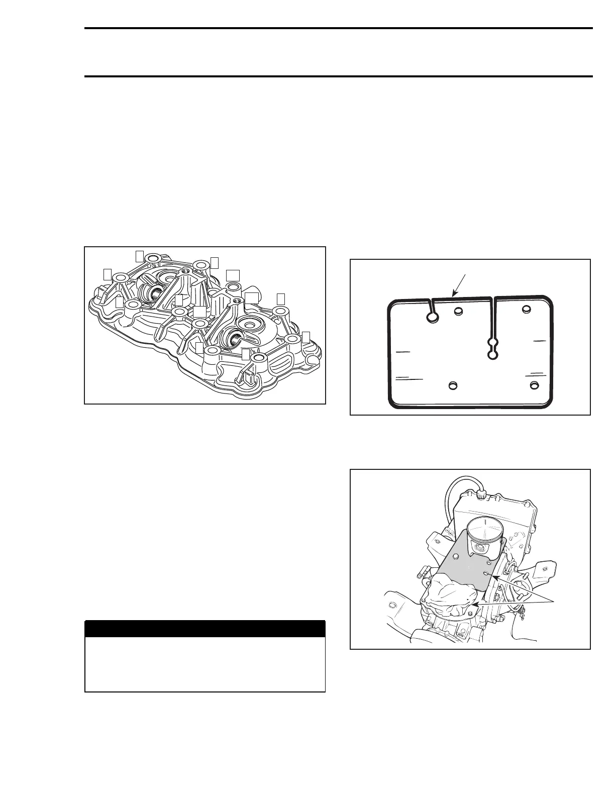
Bring piston to Top Dead Center and install rubber
pad (P/N 295 000 101) over crankcase opening.
Secure with screws. Lower piston until it sits on
pad.
F01B0JA
1
1. Rubber pad (P/N 295 000 101)
If the other cylinder has been removed, complete-
ly cover its opening with a clean rag.
F01D43A
1
1. Openings covered with rag and rubber pad
947 DI Engines
Install rubber pad (P/N 290 877 032) on crankcase.
Secure with screws. Lower piston to be removed
until it sits on pad.
smr2004-Complete Line Up 109
 Loading...


