Section 06 ENGINE MANAGEMENT (RFI)
Subsection 03 (COMPONENT INSPECTION )
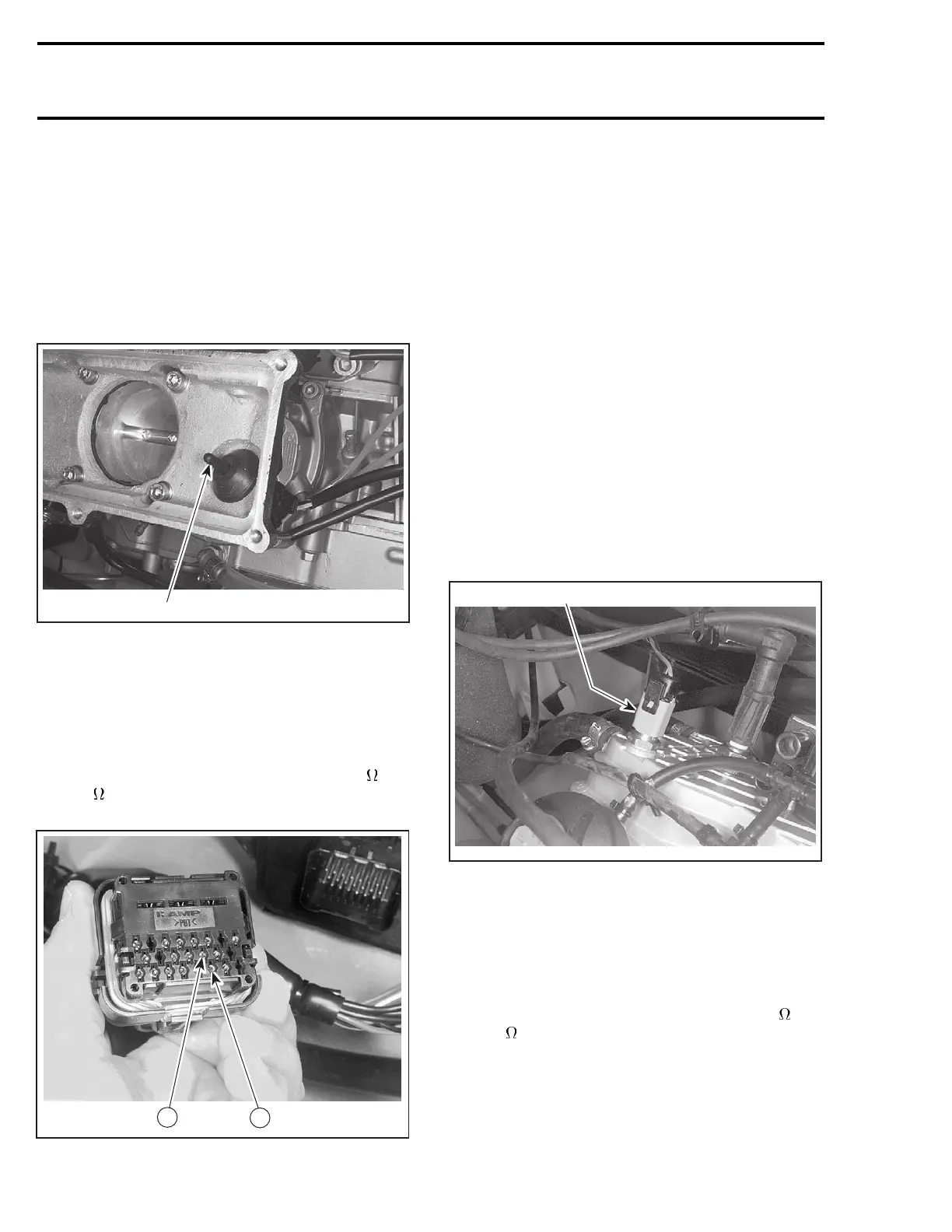
AIR TEMPERATURE SENSOR
(ATS)
NOTE: When testing the resistance of the air tem-
perature sensor (ATS), it is important to check the
ambient temperature. The resistance values for
the sensor will be different according to the tem-
perature.
Check the air temperature sensor resistance.
F07F0FA
1
1. Air temperature sensor (ATS)
Disconnect the AMP plug connector #4 from the
MPEM module.
Using a multimeter, check the resistance between
terminal 6 (BLACK/WHITE wire) and terminal 13
(WHITE/GREY wire) on the plug connector.
The resistance should be between 2.280 k
and
2.736 k
at temperature of 19°Cto21°C(66°Fto
70°F).
6
F07F15D
13
If resistance is below specifications, replace air
temperature sensor (ATS).
If resistance is above specifications, disconnect
the connector of the air temperature sensor and
check resistance of wiring harness and terminals
between AMP plug connector and ATS sensor
connector.
If there is an open circuit, repair or replace the
defective wire or terminal.
Reconnect the air temperature sensor connector
and recheck the resistance between terminal 6
and terminal 13 in the AMP plug connector #4.
If not within specification, replace the air temper-
ature sensor.
WATER TEMPERATURE
SENSOR (WTS)
Resistance Test
Check the water temperature sensor resistance.
F07F0GA
1
1. Water temperature sensor (WTS)
Disconnect the AMP plug connector #4 from the
MPEM module.
Using a multimeter, check the resistance between
terminal 5 (BLACK/ORANGE wire) and terminal 12
(TAN/ORANGE wire) on the plug connector.
The resistance should be between 2.280 k
and
2.736 k
at temperature of 19°Cto21°C(66°Fto
70°F).
314 smr2004-Complete Line Up
 Loading...


