Section 05 ENGINE (4-TEC)
Subsection 05 (PTO HOUSING/MAGNETO)
Installation
For installation, reverse the removal procedure.
However, pay attention to the following.
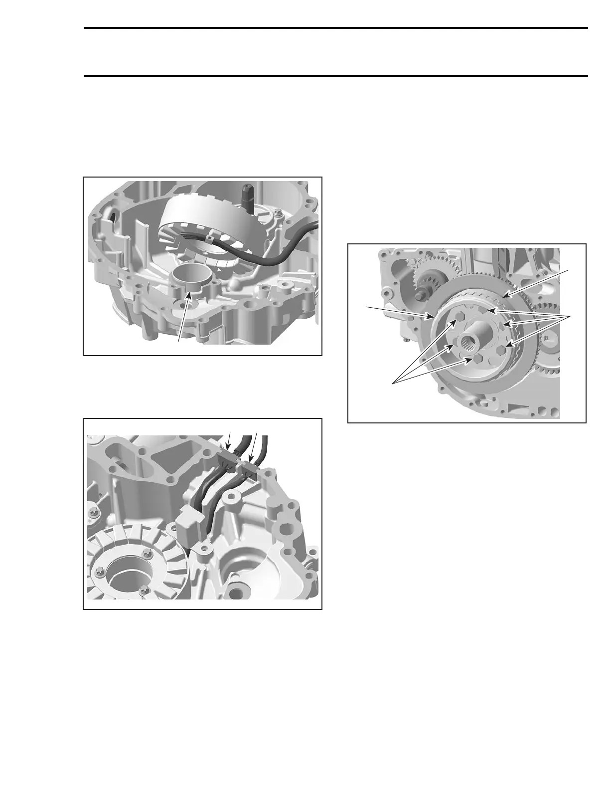
NOTE: There is only one position for the stator
(notch in the magneto housing cover).
1
R1503motr51A
TYPICAL
1. Notch for stator
Place the rubber grommets on both cables in the
proper notches at the PTO housing.
1
R1503motr52A
2
TYPICAL
1. Grommet on CPS cable
2. Grommet on stator cable
Apply Loctite 243 on threads. Torque stator and
CPSscrewsto10N•m(88lbf•in).
ROTOR AND ENCODER WHEEL
Removal
Lock crankshaft with locking tool (P/N 529 035
821). Refer to CRANKSHAFT LOCKING in EN-
GINE BLOCK subsection.
Remove:
– PTO housing
– hexagonal screws no. 18 retaining rotor.
Withdraw rotor no. 19 with encoder wheel no. 20.
1
R1503motr53A
2
3
1
TYPICAL
1. Hexagonal screws
2. Rotor
3. Encoder wheel
Inspection
Check rotor, bent teeth and encoder wheel condi-
tion. If damaged, replace faulty part.
Installation
For installation, reverse the removal procedure.
However, pay attention to the following.
Encoder wheel position has to be located with the
location pin on the crankshaft gear.
Apply Loctite 243 on threads. Torque rotor screws
to 24 N•m(17lbf•ft).
RING GEAR
Removal
Lock crankshaft with locking tool (P/N 529 035
821). Refer to CRANKSHAFT LOCKING in EN-
GINE BLOCK subsection.
smr2004-Complete Line Up 231
 Loading...


