Section12ELECTRICALSYSTEM
Subsection 03 (STARTING SYSTEM)
STARTER REMOVAL
Disconnect BLACK cable ground connection from
battery.
WARNING
Always disconnect ground cable first and re-
connect last.
Disconnect RED cable connection from battery.
717 and 787 RFI Engines
Remove the following parts:
– cables from starter
– screw no. 13 of starter rear support
– starter mount screws no. 16.
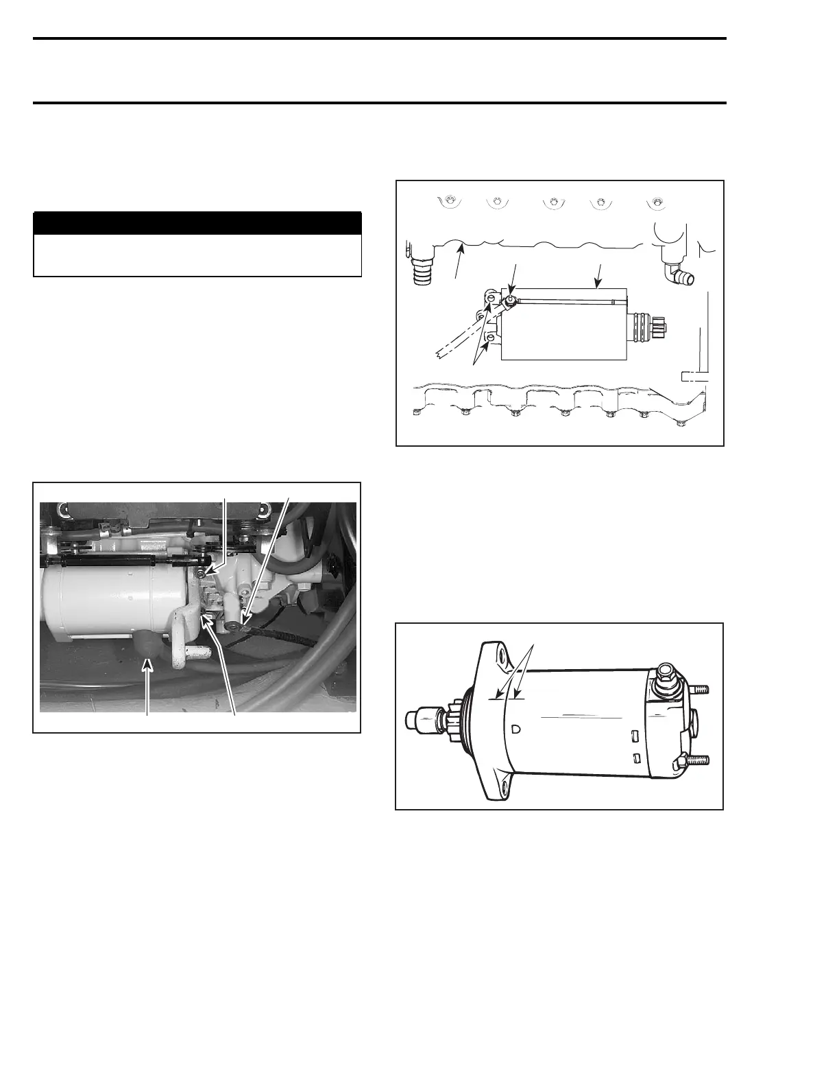
947 DI Engines
Disconnect starter cables and loosen Allen screws
no. 16 retaining starter bracket to engine.
F06H35B
2
1
3
3
1. Positive starter cable
2. Negative starter cable
3. Allen screw
Remove bracket and starter.
NOTE: To remove the starter drive assembly,
magneto flywheel has to be removed. Refer to
MAGNETO SYSTEM and BOTTOM END.
To check and replace the starter end bearing, refer
to BOTTOM END section.
4-TEC Engines
NOTE: To facilitate starter removal on RXP mod-
els, remove engine cover. Refer to BODY section.
Remove retaining screws from starter.
Pull starter out. Lift starter enough to reach starter
cable then disconnect from starter.
1
F18H0UA
24
3
1. Exhaust manifold
2. Starter
3. Retaining screws
4. Nut
STARTER DISASSEMBLY
717 and 787 RFI Engines
Before disassembling, trace index marks on yoke
no. 1 andclutchhousingno. 10 to ease further
assembly.
F01H0PA
1
TYPICAL
1. Trace indexing marks
Remove starter support nuts no. 12 then through
bolts no. 5. Separate end frame no. 3 from yoke
assembly no. 1. Withdraw yoke assembly from
armature no. 11.
Brush holder no. 2 can be removed from end
frame no. 3 by unscrewing nut retaining terminal.
580 smr2004-Complete Line Up
 Loading...


