Section 08 ENGINE MANAGEMENT (4-TEC)
Subsection 02 (COMPONENT INSPECTION AND ADJUSTMENT)
CAUTION: Probe on top of terminal only. Do
not try to probe inside terminal or to use a pa-
per clip to probe inside terminal, it can damage
the square-shaped terminal and this could lead
to unproper function of the engine managment
system.
R1503motr352A
CAUTION: Do not disconnect the ECM connec-
tor needlessly. They are not designed to be dis-
connected/reconnected repeatedly.
Engine Connector
Use this diagram to locate the terminal numbers
on the Engine connector of the wiring harness
when performing tests.
CAUTION: Before unplugging engine connec-
tor, always remove safety lanyard first then
wait 15 seconds. Otherwise, damage to CAPS
may occur.
4
R1503motr192A
1
2
3
ENGINE CONNECTOR PIN-OUT (WIRING HARNESS SIDE)
CONNECTORS ON ENGINE
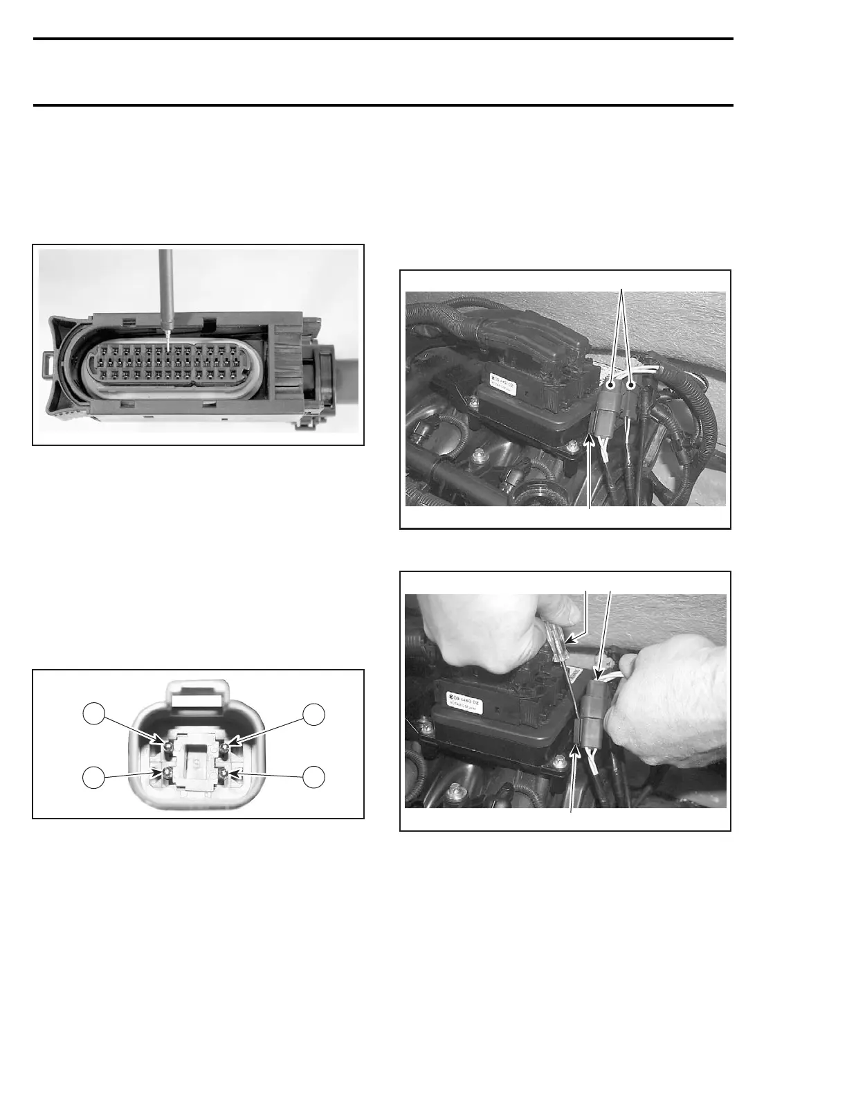
Removal
To remove connectors from engine connector
bracket, slide a flat screwdriver between the con-
nector bracket and the connectors and remove
connectors.
1
F18Z0JA
2
1. Engine connector bracket
2. Connectors
1
F18Z0KA
23
1. Engine connector bracket
2. Deutsch connector
3. Flat screwdriver
406 smr2004-Complete Line Up
 Loading...


