Section 14 STEERING SYSTEM
Subsection 01 (STEERING SYSTEM)
1
F18K1DA
3245
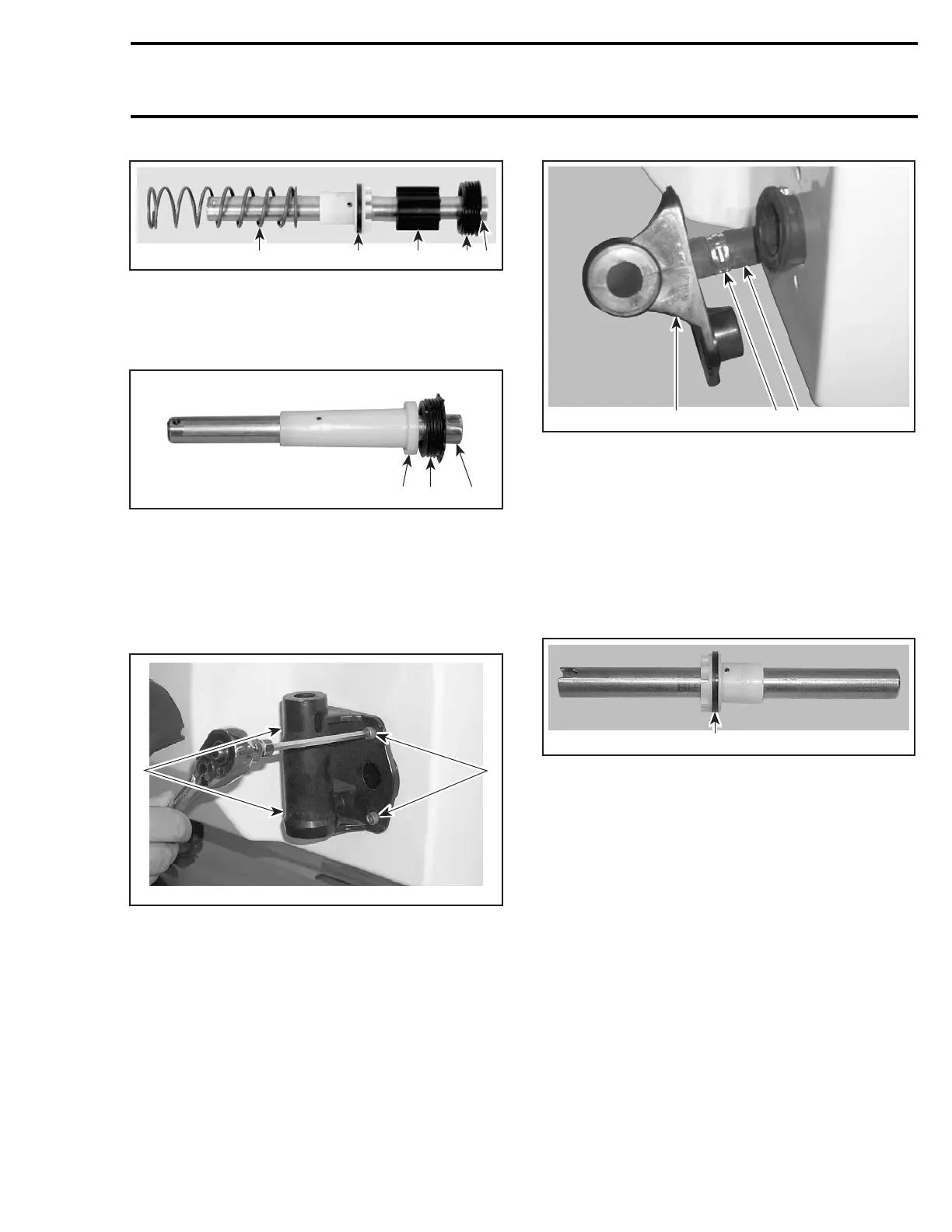
GTX 4-TEC SERIES
1. Pivot rod
2. Spacer
3. Cylinder cap assembly
4. Piston
5. Spring
1
F19J0DA
2
3
GTI SERIES AND RXP 4-TEC
1. Pivot rod
2. Spacer
3. Cylinder cap assembly
Unscrew tie rod stabilizing fitting no. 21 from tie
rod no. 23.
Unscrew 4 socket screws no. 22.
F18K0PA
1 1
1. Socket screws
GTX 4-TEC Series
Remove Oetiker clamp no. 25 to remove water
hose no. 26 from the cylinder support no. 12.
3
F18K0QA
1
2
1. Oetiker clamp
2. Water hose
3. Cylinder support
Assembly
Assembly is the reverse process of disassembly,
make sure of the following when doing assembly:
GTX 4-TEC Series
– Always discard old threaded cover rod no. 14
and replace with new one.
1
F18K0YA
1. Replace threaded cover
– Check pivot rod no. 13 for cracks or scratches.
Replace pivot rod, if necessary.
– Replace the cylinder seal ring whenever servic-
ing.
All Models
– Socket screws no. 22 should be turned 2-3
turnsbyhandbeforetighteningwithtool.
– Torque socket screw no. 22 to 5.5 N•m
(49 lbf•in).
TIE ROD
Disassembly
Removal procedure for RH and LH tie rod is same.
Remove side vane and cylinder support assembly
as mentioned above.
smr2004-Complete Line Up 705
 Loading...


