Section 08 ENGINE MANAGEMENT (4-TEC)
Subsection 02 (COMPONENT INSPECTION AND ADJUSTMENT)
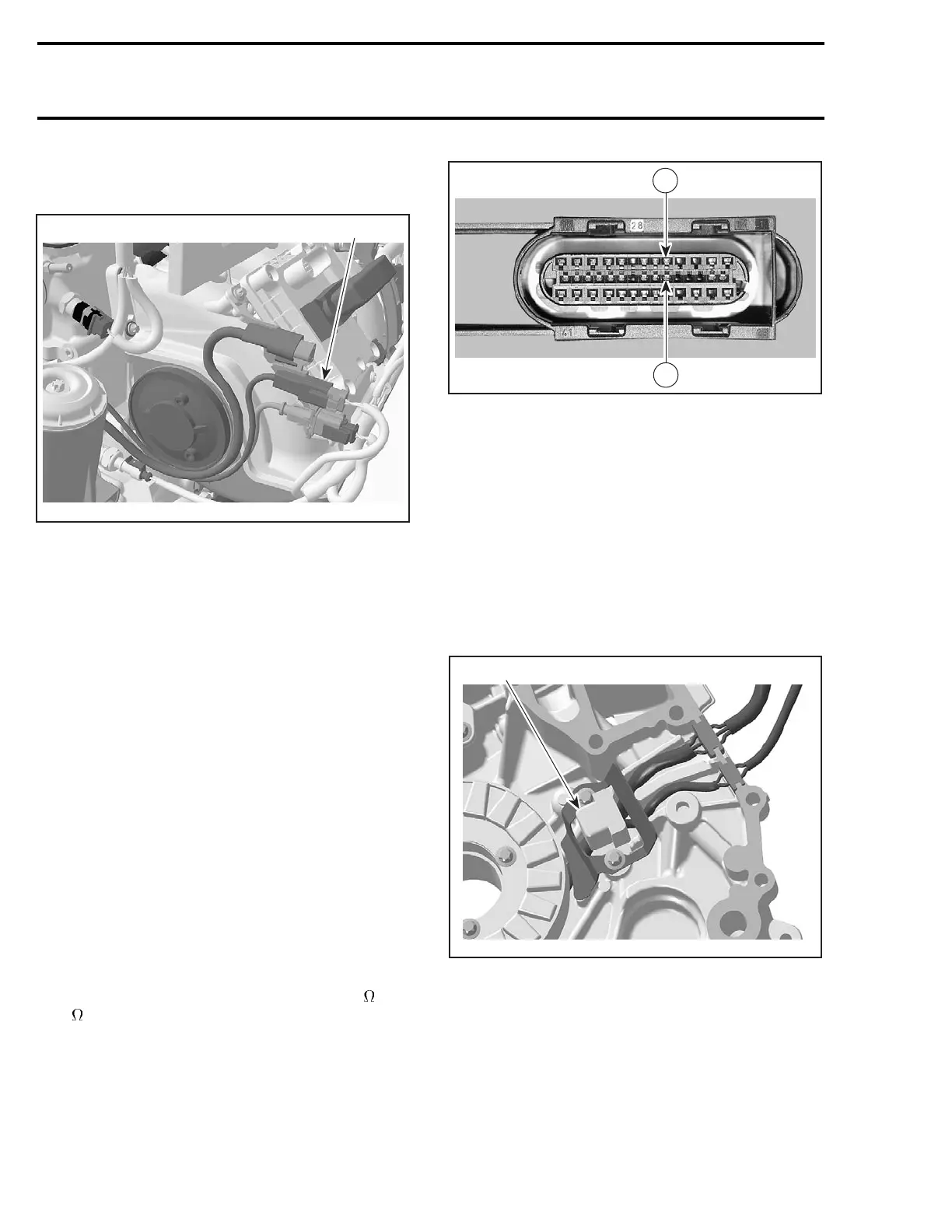
CRANKSHAFT POSITION
SENSOR (CPS)
1
R1503motr169A
TYPICAL
1. CPS connector
Ensure that information center works. Needles
will sweep, LED and LCD segments will turn on
when the safety lanyard is installed. Check for
RPM display at the information center while crank-
inginenginedrownedmode. PressandHOLD
throttle lever then press start/stop button. 800-
1000 RPM should display. Otherwise perform the
following tests.
NOTE: Take into account that a CPS fault can be
triggered by bent or missing encoder wheel teeth.
First check fault codes then check the teeth con-
dition if necessary. See below.
Disconnect CPS wiring harness connector. Probe
terminals coming from CPS while cranking engine.
Voltage should be within 1-2 Vac. Otherwise, in-
spect wiring and replace CPS if wiring is good.
Resistance Test
Disconnect the CPS connector from the wiring
harness and check the resistance of the sensor
itself.
The resistance should be between 190
and
290
.
Otherwise, replace the CPS.
If resistance tests good, reconnect the CPS and
disconnect the ECM connector A on the ECM.
Using a multimeter, recheck resistance value be-
tween terminals 5 and 19.
R1503motr182A
5
19
If resistance value is correct, try a new ECM. Refer
to ECM REPLACEMENT procedures elsewhere in
this section.
If resistance value is incorrect, repair the connec-
tors or replace the wiring harness between ECM
connector and the CPS.
Replacement
Disconnect connectors and remove the PTO
cover. Refer to PTO HOUSING/MAGNETO in
ENGINE section.
Remove CPS.
1
R1503motr170A
1. CPS inside PTO cover
Apply Loctite 243 on screw threads then install the
new CPS. Torque to 10 N•m(89lbf•in).
Reinstall remaining removed parts.
Encoder Wheel Inspection
To check the encoder wheel for bent teeth, pro-
ceed as follows.
424 smr2004-Complete Line Up
 Loading...


