Section 07 ENGINE MANAGEMENT (DI)
Subsection 02 (COMPONENT INSPECTION AND ADJUSTMENT)
CAUTION: Failure to properly clean the oil sys-
tem will result in serious engine damage.
The inspection of top end should include the fol-
lowing measurements.
TOLERANCES
ENGINE
MEASUREMENT
NEW PARTS
(min.) (max.)
WEAR
LIMIT
Piston/cylinder
wall clearance
0.12 mm
(.005 in)
N.A.
0.2 mm
(.008 in)
Ring end gap
0.1 mm
(.004 in)
0.25 mm
(.010 in)
0.5 mm
(.020 in)
N.A.: NOT APPLICABLE
Piston/Cylinder Wall Clearance
Clearance can be quickly checked with a feeler
gauge. Insert feeler gauge in cylinder then slide
piston (without piston rings installed). If clearance
exceeds tolerance, check cylinder top area with
your finger to feel if there is a ridge. If so, the
cylinder sleeve is worn and needs replacement.
Otherwise, replace piston.
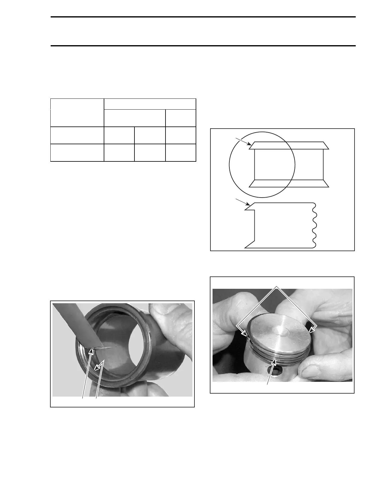
Ring End Gap
Position ring close to top of cylinder top.
NOTE: In order to correctly position ring in cylin-
der, use piston as a pusher.
Using a feeler gauge, check ring end gap. If gap
exceeds specified tolerance, rings should be re-
placed.
21
F12R07A
1. Top of cylinder
2. Ring end gap
Assembly
Apply injection oil in cylinder and on rings prior to
installing.
Install the oil ring with the “TOP” markingontop.
Identify the correct position by looking at beveled
edge of oil ring and while installation, make sure
that the beveled edge is towards the top of the
piston.
1
F12R1OA
1
1. Beveled edge
Position ring openings 180° apart.
2
F12R15A
1
1. Ring openings 180° apart
2. TOP marking on this side
Use ring compressor (P/N 529 035 713) and insert
piston in cylinder.
NOTE: Cylinder may be removed from crankcase
to install piston more easily from the bottom.
smr2004-Complete Line Up 345
 Loading...


