Section 08 ENGINE MANAGEMENT (4-TEC)
Subsection 01 (OVERVIEW)
R1503motr266T
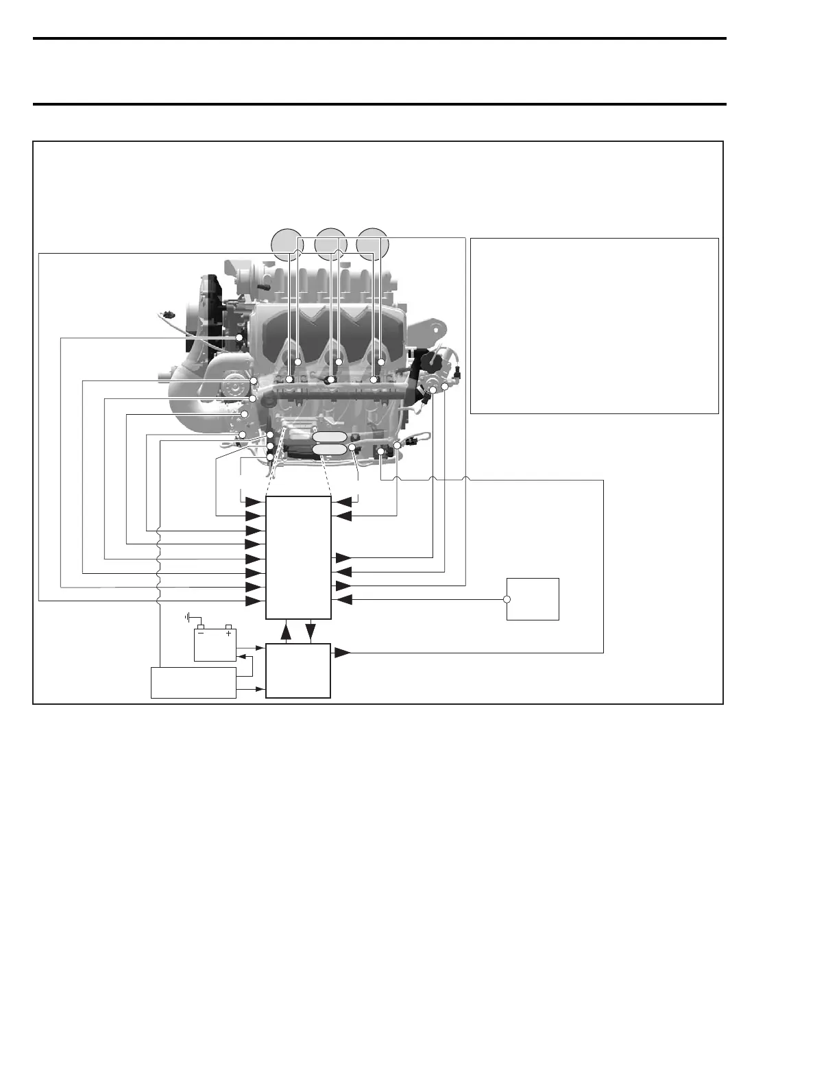
ENGINE MANAGEMENT SYSTEM - OVERVIEW
ROTAX 1503 4-TEC SUPERCHARGED
ECM
KS
CPS
OPS
CTS
CAPS
INJECTOR 1,2,3
MAPS
MATS
IDLE
BYPASS VALVE
TPS
IGNITION COIL
OSPS
TOPS VALVE
EGTS
MPEM
REGULATOR/
RECTIFIER
MUFFLER
Cyl.1 Cyl.2 Cyl.3
MAGNETO
ENGINE POWER SUPPLY
ECM ECM Engine Control Module
MPEM Multi-Purpose Electronic Module
KS Knock Sensor
CPS Cranshaft Position Sensor
OPS Oil Pressure Sensor
OSPS Oil Separator Pressure Sensor
CTS Coolant Temperature Sensor
CAPS Camshaft Position Sensor
EGTS Exhaust Gas Temperature Sensor
MAPS Manifold Air Pressure Sensor
MATS Manifold Air Temperature Sensor
TOPS Tip-Over Protection System
Con.A Connector for Engine Wiring Harness
Con.B Connector for MPEM Connection
BATTERY
Con. A
Con. B
The complete electrical system is managed by
micro-controllers working together. Overall, the
MPEM (multi-purpose electronic module) man-
ages the vehicle electrical system, the EMS
(engine management system) controls the en-
gine management and the information center is
used to display information that comes both from
MPEM and EMS.
A communication link is used between the elec-
tronic modules to communicate with each other.
It consists of a twisted pair of wires (WHITE/RED
and WHITE/BLACK).
For communication link troubleshooting, refer to
INSTRUMENTS AND ACCESSORIES in ELECTRI-
CAL section.
Thecommunicationlinkisalsousedtocommuni-
cate informative messages, monitoring and diag-
nostic codes to the information center and to the
VCK (vehicle communication kit) where B.U.D.S.
(Bombardier utility and diagnostic system) is used
for diagnosing and troubleshooting the system.
The fault code can be seen from either the infor-
mation center or B.U.D.S. Refer to DIAGNOSTIC
PROCEDURES section.
392 smr2004-Complete Line Up
 Loading...


