146
Manual – MOVIDRIVE® MDX61B Safety Module MOVISAFE® DCS..B Option
12
Typical response times
Appendix
12.6.2 Typical response times of the DCS31B option
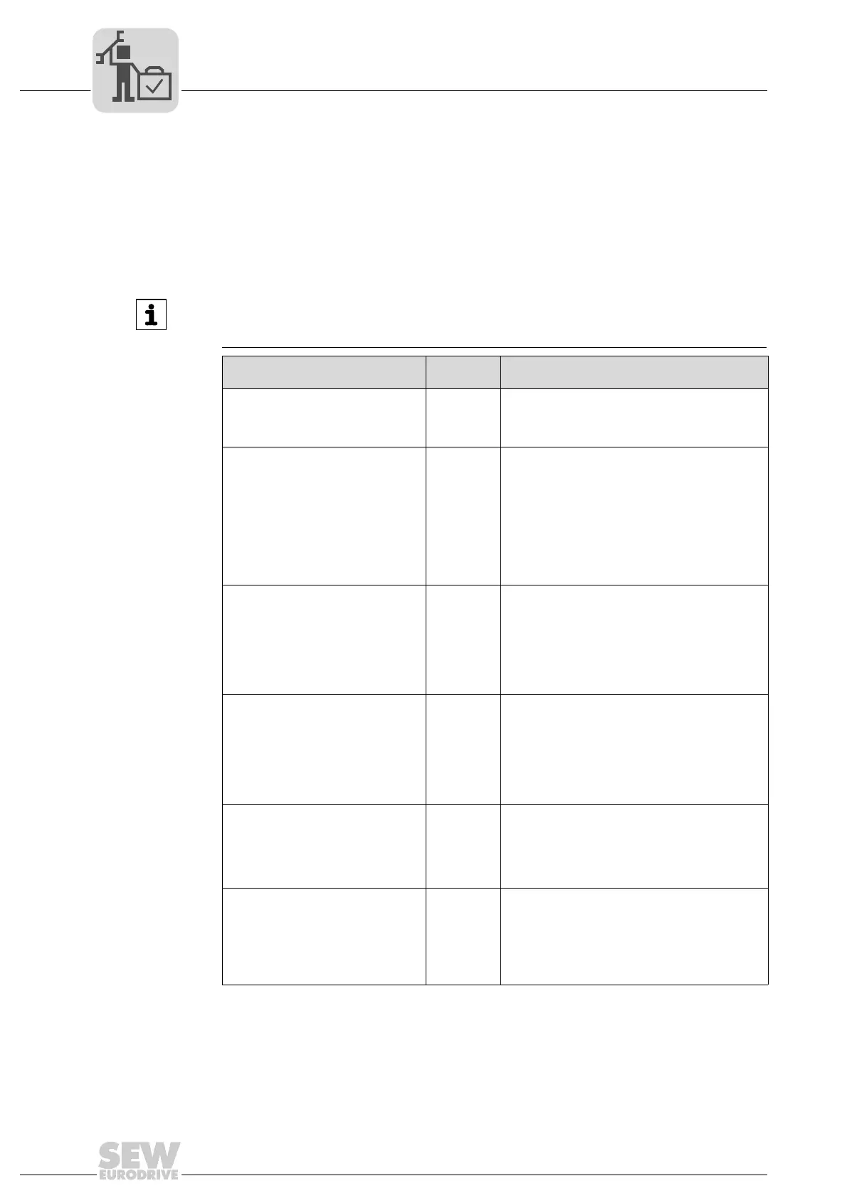
The following table lists the response times of the DCS31B option.
The calculation of response times is based on the cycle time of the system. The cycle
time (T_cycle) of the DCS31B option is 25 ms. The specified response times correspond
to the maximum run time for the specific application within the DCS31B option.
Depending on the application, additional application-specific response times for the
sensors and actuators used have to be added to get the total run time.
INFORMATION
If the "overspeed distance monitoring" filter is used, the response time will increase
depending on the set distance.
Function Response
time [ms]
Explanation
Reading-in a digital NC contact and
further processing by the internal
safety controller
58 The DCS31B option recognizes an NC contact
within one cycle. Another cycle is needed for
further processing including the switching of an
output.
Reading-in a digital NO contact and
further processing by the internal
safety controller
75 For a NO contact to be recognized as active ("1"),
an active signal level must be present at the input
for an entire clock cycle of the DCS31B option. In
the worst case, sampling will take two cycles to
make relevant information available for internal
processing. As another cycle is needed for
processing the input signal, this results in a total
signal run time of three cycles.
Note: Try to avoid using NO contacts in safety
circuits!
Response of an already activated
monitoring function including logic
processing for position and speed
processing
50 For a monitoring function that has already been
activated via ENABLE, the DCS31B option needs
one cycle to calculate the current speed value. In
the next cycle, the information is further processed
and output by the PLC after the monitoring function
has been calculated. This can lead, for example, to
the switching of an output once the programmed
logic has been performed.
Response of an already activated
monitoring function including logic
processing for acceleration
processing
75 For a monitoring function that has already been
activated via ENABLE, the DCS31B option needs
two cycles to calculate the current acceleration
value. In the next cycle, the information is further
processed and output by the PLC after the
monitoring function has been calculated. This can
lead, for example, to the switching of an output
once the programmed logic has been performed.
Response of a monitoring function
activated by an external input includ-
ing processing of the safety controller
when using a NC contact.
83 The input signal processing lasts one scan cycle.
Another cycle is needed to set the ENABLE input
for the required monitoring function. In the next
cycle, the monitoring function and behavior of the
result is calculated and, if necessary, the output is
activated.
Response of a monitoring function
activated by an external input
including processing of the safety
controller when using a NO contact.
100 For processing the digital input signal, two cycles
are required in the worst case. Another cycle is
needed for setting the ENABLE input of the
required monitoring function. In the next cycle, the
monitoring function and processing of the result is
calculated and, if necessary, the output is acti-
vated.
 Loading...