Manual – MOVIDRIVE® MDX61B Safety Module MOVISAFE® DCS..B Option
49
5
Connecting binary inputs DI1 to DI8
Installation
5.8.1 Using pulse outputs
The DCS..B option provides two pulse outputs P1 (X81:2) and P2 (X81:6) on the X81
terminal strip in addition to binary inputs DI1 to DI8. The P1 and P2 pulse outputs are
switching DC 24 V outputs that are intended exclusively for monitoring the binary inputs
(DI1 – DI8). The pulse outputs must not be used for other functions within the applica-
tion. For project planning, note that the connected cables do not exceed the maximum
length of 30 m and that the maximum permitted total current for the pulse outputs does
not exceed 300 mA.
Each digital input of option DCS..B can be configured individually for the following signal
sources:
• Digital input is assigned to pulse P1
• Digital input is assigned to pulse P2
• Digital input is assigned to DC 24 V continuous voltage
An alternating assignment is recommended (see below table).
INFORMATION
Without using pulsing, the binary inputs can be connected as follows:
• With single-channel, self-monitoring sensors, you can establish structures up to
category 2. This means you can achieve a performance level in accordance with
EN ISO 13849-1.
• With dual-channel sensors without function test within 24 hours, you can establish
structures up to category 3. This means you can achieve a performance level in
accordance with EN ISO 13849-1.
• With dual-channel sensors and function test within 24 hours, you can establish
structures up to category 4. This means you can achieve a performance level in
accordance with EN ISO 13849-1.
Note that external measures, especially suitable cable routing, are necessary to
prevent a short circuit in the external wiring between different inputs and against
the supply voltage of the DCS..B.
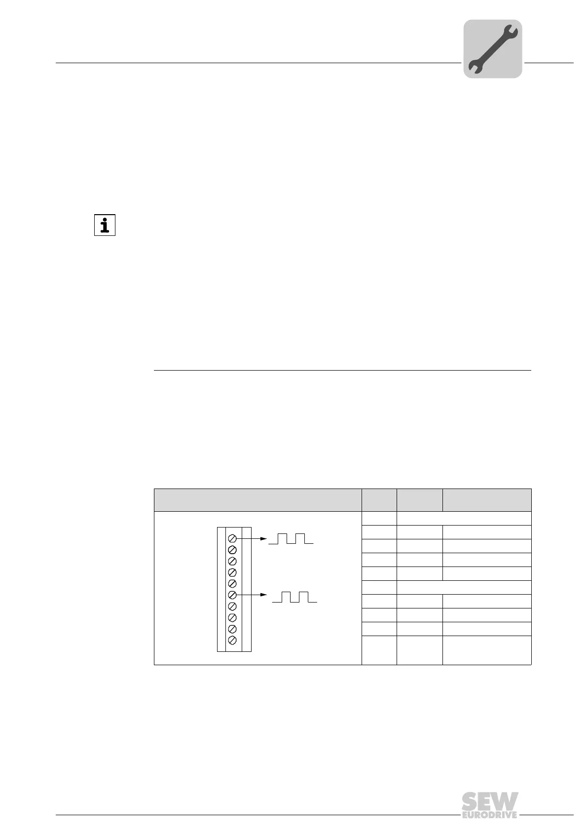
Pulse outputs P1, P2 Pin Assign-
ment
Remark
9007201226326155
X81:1 Pulse 1 output (P1)
X81.2 DI1 Pulse 2 assigned
X81:3 DI2 Pulse 1 assigned
X81:4 DI3 Pulse 2 assigned
X81:5 DI4 Pulse 1 assigned
X81:6 Pulse 2 output (P2)
X81:7 DI5 Pulse 1 assigned
X81:8 DI6 Pulse 2 assigned
X81:9 DI7 Pulse 1 assigned
X81:10 DI8 Pulse 2 assigned
P1
P2
DI1
DI2
DI3
DI4
DI5
DI6
DI7
DI8
X81
1
6
2
3
4
5
7
8
9
10
 Loading...