Manual – MOVIDRIVE® MDX61B Safety Module MOVISAFE® DCS..B Option
63
5
Connecting the position and velocity sensors
Installation
5.10 Connecting the position and velocity sensors
5.10.1 Before you start
The DCS..B option has two encoder interfaces for connecting standard TTL incremen-
tal, sin/cos, and SSI absolute encoders.
TTL Incremental, sin/cos or SSI absolute encoders (binary or Gray code) can be
connected and operated using the same encoder interface, and the encoder values of
MOVIDRIVE
®
B can be used via backplane bus. The encoder parameters are set using
the MOVISAFE
®
Assist/Config software interface.
Different safety levels can be achieved depending on the encoder type and combination.
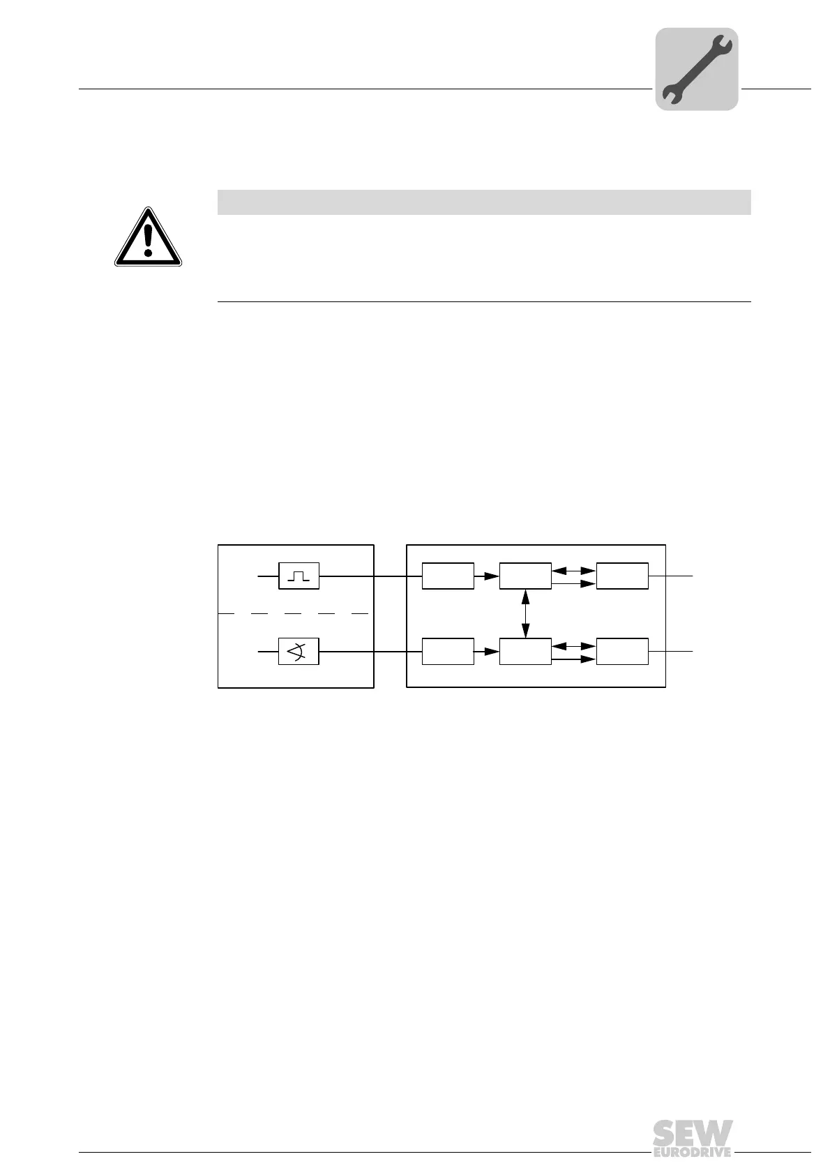
The following system view applies to the respective subsystem.
Example:
Dual-channel sensor system with separate signal processing in two channels, diagnos-
tics by means of cross comparison in the DCS..B option (PES).
NOTICE
Do not plug in or remove encoder connections during operation.
Doing so can cause irreparable damage to the electrical components on the encoder.
Disconnect the connected encoders and the DCS..B option before plugging in or
removing the encoder connections.
2408487691
PES = Programmable electronic system
I
A
= Input channel A
I
B
= Input channel B
L
A
= Logic channel A
L
B
= Logic channel B
O
A
= Output channel A
O
B
= Output channel B
c = Cross comparison
m = Monitoring
S
A
= Sensor 1 channel A
S
B
= Sensor 2 channel B
Sensor
S
A
S
B
I
A
O
A
L
A
I
B
O
B
L
B
c
PES
m
m
 Loading...