•
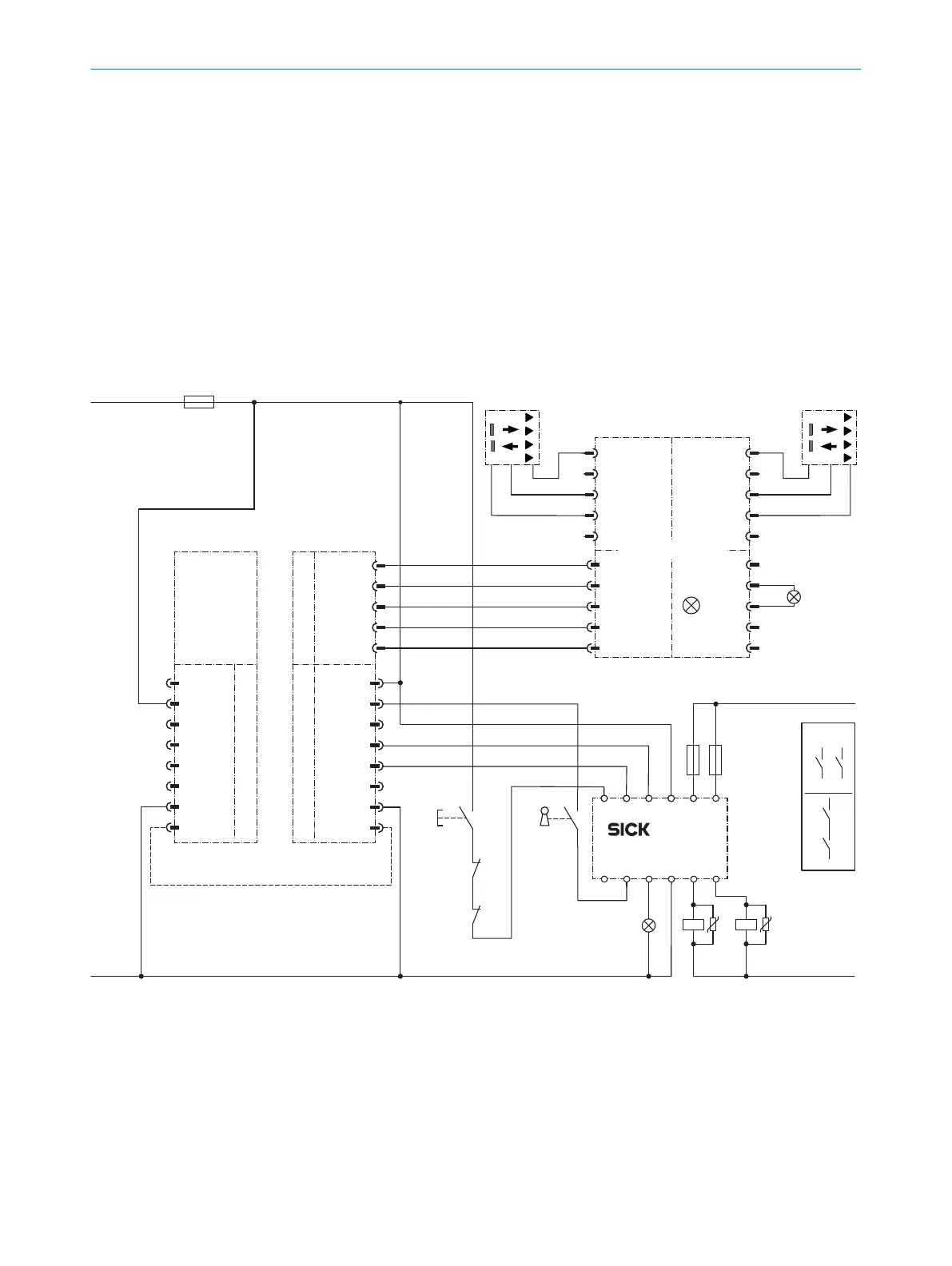
Mode of opera
tion
If the protective field is clear and the RLY3-OSSD1 is in a fault-free, de-energized
posit
ion, the system is enabled. Outputs OSSD 1 and OSSD 2 carry voltage, the
RLY3-OSSD1 is switched on. The outputs (contacts 13-14 and 23-24) switch the
K1 and K2 contactors on. When the protective field is interrupted, the OSSD 1 and
OSSD 2 outputs switch the RLY3-OSSD1 off. Contactors K1 and K2 are switched
off. Status and fault information, as well as diagnostics data, can be transferred
directly to an IO-Link master via IO-Link connectors.
•
F
ault analysis
Cross-circuits and short-circuits of the OSSDs are recognized and lead to the
loc
king status (lock-out). A malfunction with one of the K1 or K2 contactors is
detected. The switch-off function is retained.
Muting, RLY3-OSSD2 safety relay, with SP2 system plug
E202113/01/2021-09-27
r
A1 A2
n.c.
0 V Out
+24 V Out
ADO
n.c.
MUT 2
0 V Out
+24 V Out
n.c.
n.c.
5
4
2
1
3
MUT 1
0 V Out
+24 V Out
n.c.
n.c.
(Reset) (Override)
(Reset required)
(Muting)
Out 2
0 V DC
+24 V DC
Out 1
C
om 2
5
4
2
1
3
5
4
2
1
3
5
4
2
1
3
Muting connector
+24 V Out
In 1
0 V Out
System connection
System connection
Extension connection
In 2
MFP 2
+24 V DC
deTec4 SP2
A1 A2
1
2
3
4
5
2
1
3
5
6
4
7
8
r
RES/OVR
ADO
OSSD 1
OSSD 2
EDM
0 V DC
MFP 1
s
n.c.
+24 V DC
n.c
In 2
n.c.
0 V DC
MFP 1
In 1
1
2
3
4
5
6
7
8
F2 F1
H1
H2
+24 V DC
0 V DC
K2
K1
R1 Y1 Y2 24A2 14
S
1 I1 I2 23A1 13
RLY3-OSSD2
k2
k1
S1
Q – + Q–+
k2
z
k1 k2
k1
z
x y
x
1)
y
S2
2)
3)
PELV
L+
L–
F0
1) Output circuits: These contacts must be incorporated into the control such that the
d
angerous state is brought to an end if the output circuit is open. For categories 4 and 3,
they must be incorporated on dual-channels (x, y paths). Type 2 devices are suitable for
use up to PL c. Single-channel incorporation into the control (z path) is only possible with
a single-channel control and taking the risk analysis into account.
2) To indicate the status on both sides, the MFP 1 connections from the sender and receiver
must be connected to each other in the control cabinet (optional).
3) SELV/PELV safety extra-low voltage.
•
T
ask
4 P
ROJECT PLANNING
70
O P E R A T I N G I N S T R U C T I O N S | deTec4 8021645/1EB0/2022-04-28 | SICK
Subject to change without notice