Assembly and Installation
FLOWSIC100 Flare · Operating Instructions · 8013344/11L2/V 2-5/2018-10 · © SICK Engineering GmbH 141
Subject to change without notice
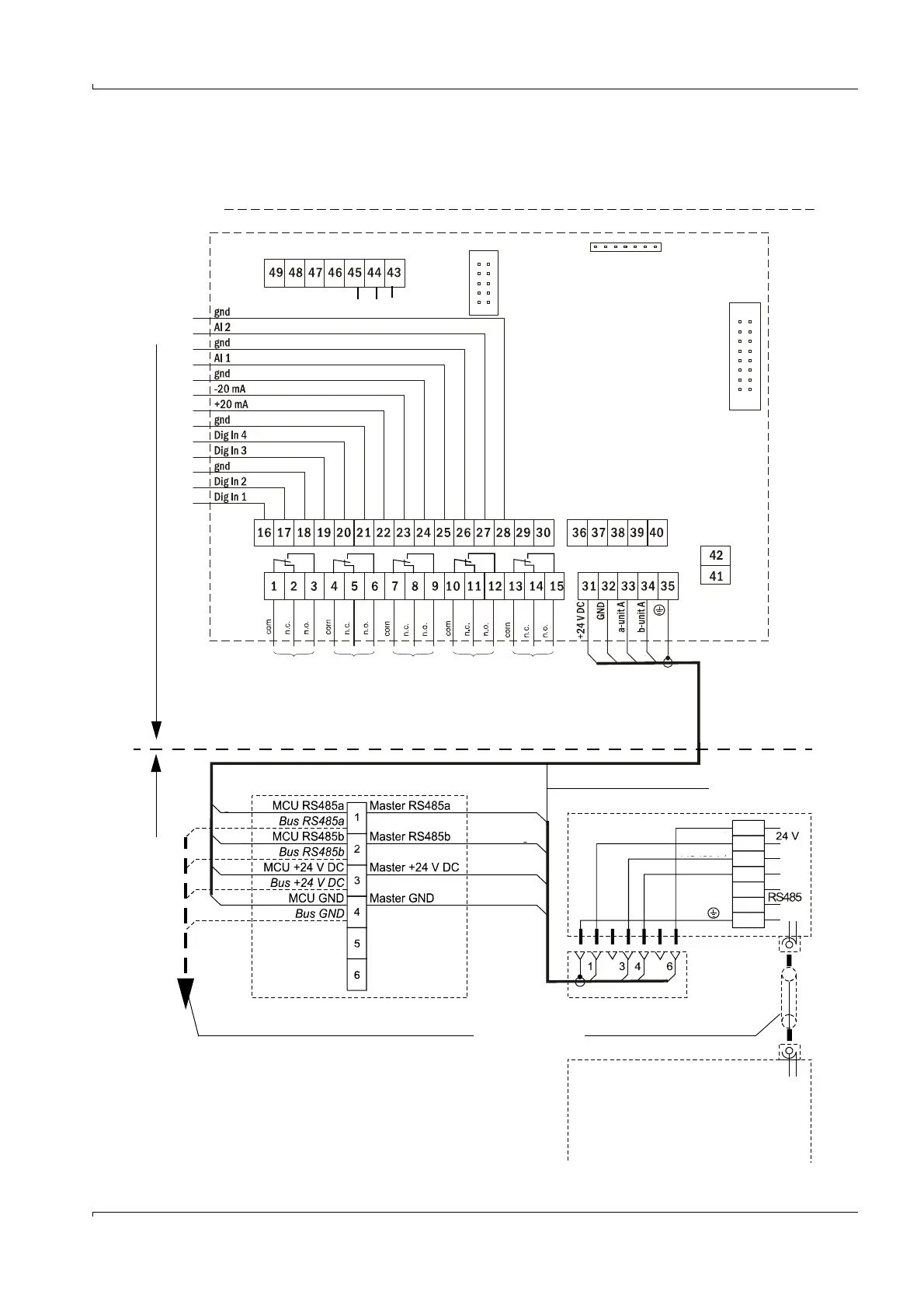
Bus standard cabling (MCUP without explosion protection version or version for Ex zone
2)
- Example for device type FL100 EX-S
Fig. 71 Connection of sender/receiver units to the MCUP (bus standard cabling)
MCUP Processor board
FLSE100-EXS digital
Cable provided by customer
Connection cable analog to Exi
FLSE100-EXS analog
Junction box
1)
Cable provided by customer to second junction box
(Contact position in current-free state)
Ex zone Safe area (or Ex zone 2 for MCUP in Ex zone 2 version)
green
yellow
white
brown
green
yellow
white
brown
green
yellow
white
brown
white
brown
green
yellow
gnd
+24 V DC
RS485a
RS485b
A Operation/malfunction
B Maintenance
C Check cycle
D Maintenance request
E Limit value
A
BC D
E
1)
: For Ex zone 2 with optional Exe junction box
(on request)
For Ex zone 1 only with approved junction box
Exi or junction box Exd
2): MCUP Ex zone 2 only
*: Not for FLSE100-EXPR
**: MCUP Ex zone 2 only
Service
RS485
2
gnd B A
Connection Interface module
Connection display