Assembly and Installation
FLOWSIC100 Flare · Operating Instructions · 8013344/11L2/V 2-5/2018-10 · © SICK Engineering GmbH 147
Subject to change without notice
3.8.7.2 MCUP in 19” rack
Plug optional analog and digital modules on the slots in the module carrier beginning with
plug-in place 1 in the order AO
→ AI → DO → DI without gap. If single module types are not
available, the next respective one follows according to the order mentioned.
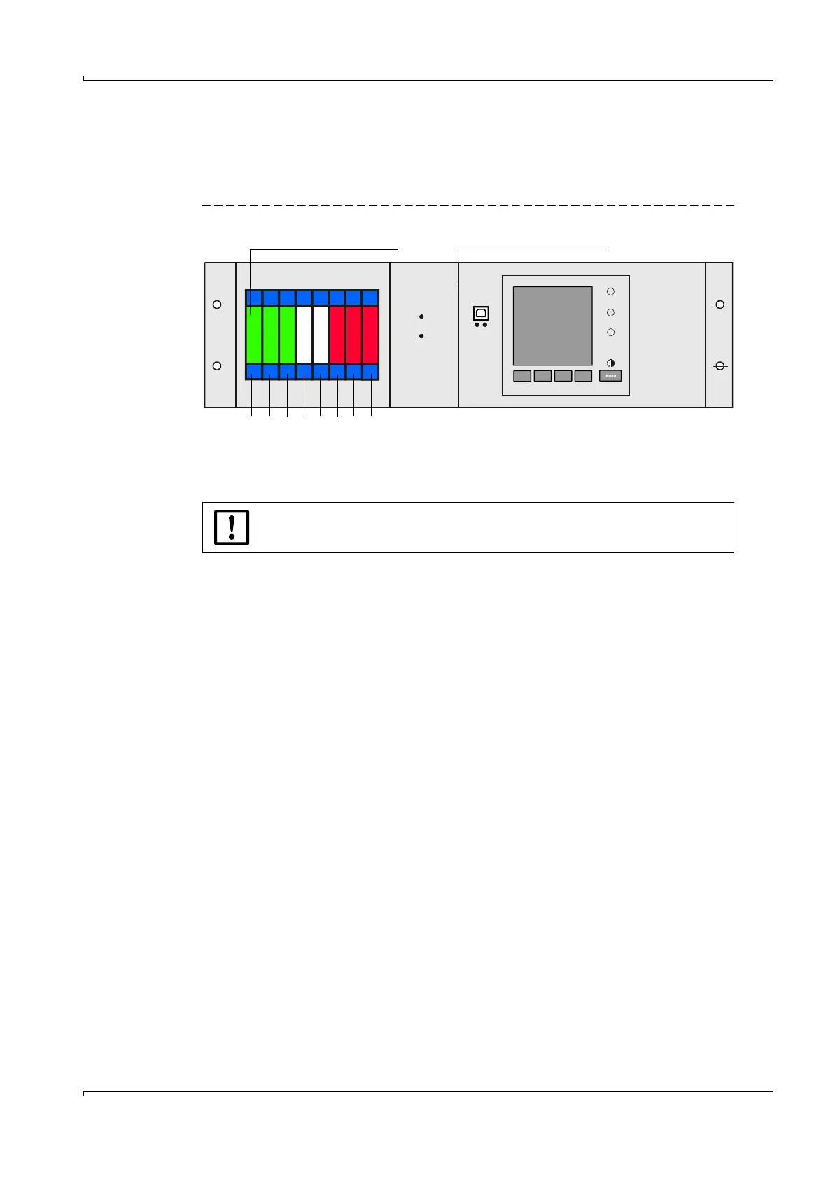
Fig. 80 Slots for optional modules
The MCUP contains 8 slots for optional I/O modules. The connection of these modules
(analog and digital types) is carried out at the terminals 101-180.
Following this, the connection of the modules is represented exemplarily to slot 1.
The connection of optional modules (analog and digital type) at the other slots 2-8 is
carried out in the same way.
REQUEST
INTERFACE-MODULE
I/O-MODULE
POWER
ERROR
TxD RxD
Slots for optional I/O modules Slot for interface module option
8 7 6 5 4 3 2 1
Slot
NOTICE:
Screw-fixed terminals for wire size 0.5 .. 2.5 mm² (AWG20 ... AWG12).