Assembly and Installation
FLOWSIC100 Flare · Operating Instructions · 8013344/11L2/V 2-5/2018-10 · © SICK Engineering GmbH 93
Subject to change without notice
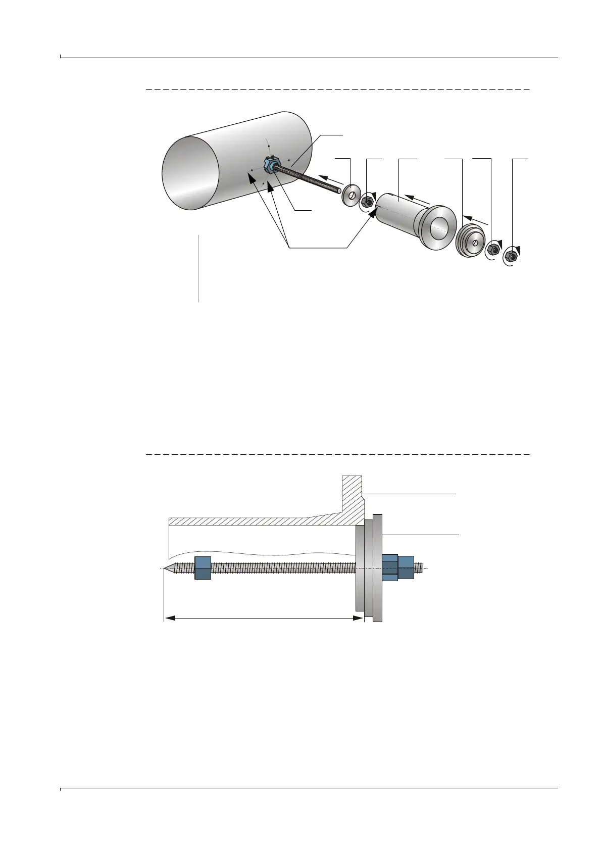
Fig. 41 Fitting the nozzle
Weld the nozzle to the pipeline (seam length approx. 15 mm). Wait at least 1 minute
after each welding to allow the seam to cool down before welding the next point.
Remove uncoated wire.
Remove threaded rod with nuts and centering by turning the counternut (8) against fas-
tening direction. The centering plate will be removed by the clamp ring.
Finish off each weld seam and allow sufficient time for cooling down to avoid unneces-
sary strain on the nozzle and pipe wall.
On FLOWSIC100 Flare cross-duct versions (FLSE100-EX and FLSE100-EXS) and after
sufficient time for cooling down, determine distance D1 between outer pipe wall and
centering.
Fig. 42 Determining of effective nozzle length
On cross-duct versions, weld the nozzle on the opposite pipeline side in the same man-
ner and then determine distance D2.
Marking lines
4 5 6 7 8 9
1
1 Welding aid
4 Centering plate
5 Nut
6 Nozzle
7 Centering
8,9 Counter nuts
10 Clamp ring
10