Minimum Typical Maximum
Sine-cosine analog voltage monitor‐
in
g
12)
, lower limit for vector length
monitoring
10)
0.5V
PP
0.55V
PP
–
Sine-cosine analog voltage monitor‐
ing
12)
, upper limit for vector length
monitoring
10)
– 1.26V
PP
1.5V
PP
Accuracy error affecting speed detec‐
tion
13)
Max. 5% incl. the internal resolution of the speed infor‐
mation
Accuracy error affecting position
de
tection
14)
Max. 1 increment of the internal resolution of the posi‐
tion information
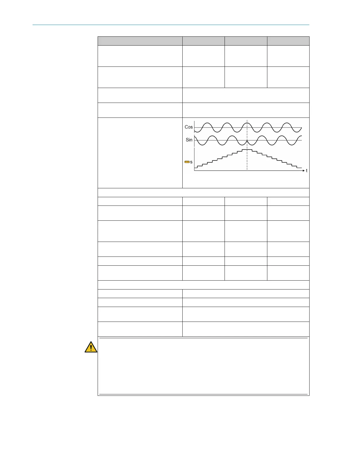
Counting direction
S = position information
SSI encoder (ENCx_A+, ENCx_A–, ENCx_C+, ENCx_C–, ENC_0V)
Baud rate
15)
16)
100kHz – 1MHz
Clock gap between data packages
(mono f
lop time)
17)
100µs – –
Synchronization SSI Clock for SSI
master between encoder1 and
encoder2
–1ms – 1ms
“Max. data reception interval”
parameter tolerance
16)
–0.5ms – 0.5ms
Number of position data bits
16)
18)
8 – 32
Number of bits of the complete SSI
pr
otocol frame
16)
18)
8 – 62
Changing the position information (speed) per max. data reception interval
16)
19)
≤16 position data bits
16)
Max. ½ value range of position data bits – 1 increment
≥ 17 position data bits
16)
Max. 65,535 increments
Accuracy error affecting speed detec‐
t
ion
20)
Max. 5% incl. the internal resolution of the speed infor‐
mation
Accuracy error affecting position
de
tection
21)
Max. 1 increment of the internal resolution of the posi‐
tion information
WARNING
Incor
rect data is output if the maximum speed is exceeded
The dangerous state may not be stopped or not be stopped in a timely manner in the event of
non-compliance.
The target safety-related level may not be achieved in the event of non-compliance.
►
Observe maximum speed.
►
Only use suitable encoders for the application.
1)
Resistance between ENCx_y+/– and ENC_0V.
2)
Resistance between ENCx_y+/– and ENC_0V. An input voltage of 30V between ENCx_y+/– and ENC_0V
w
ill not damage the module; e.g., if the voltage exceeds 5V in the event of voltage limiting.
3)
Resistance between ENCx_y+ and ENCx_y– with series capacitor to block direct current load. An input
voltage of 30V will not damage the module.
TECHNICAL DATA 12
8012478/1IG6/2023-02-24 | SICK O P E R A T I N G I N S T R U C T I O N S | Flexi Soft Modular Safety Controller
163
Subject to change without notice