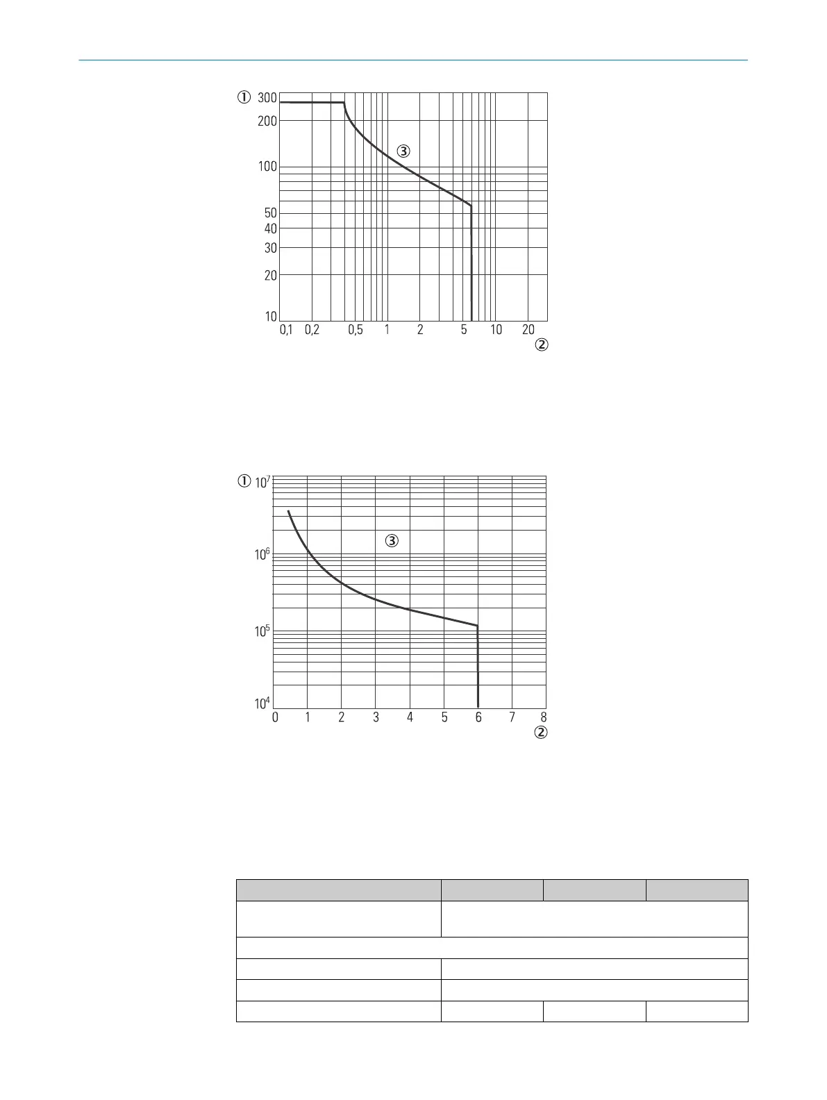
Figure 68: Maximum switching voltage with direct current, relay modules UE410-2RO/
UE410-4R
O
1
DC voltage [V DC]
2
Direct current [A]
3
Resistive load
Figure 69: Electrical endurance of relay modules UE410-2RO/UE410-4RO
1
Switching operations
2
Switching current [A]
3
250 V AC resistive load with 1 N/O contact
Table 185: Output circuit (Y14, Y24) of the UE410-2RO/UE410-4RO
Minimum Typical Maximum
Type of output Normally open contact on internal 24V DC, positively
guided
, current limited
Number of normally open contacts Y14/24
UE410-2RO 1
UE410-4RO 2
Output voltage 16V DC +24VDC 30V DC
TECHNICAL DATA 12
8012478/1IG6/2023-02-24 | SICK O P E R A T I N G I N S T R U C T I O N S | Flexi Soft Modular Safety Controller
169
Subject to change without notice