3.4.6.1 Internal circuitry
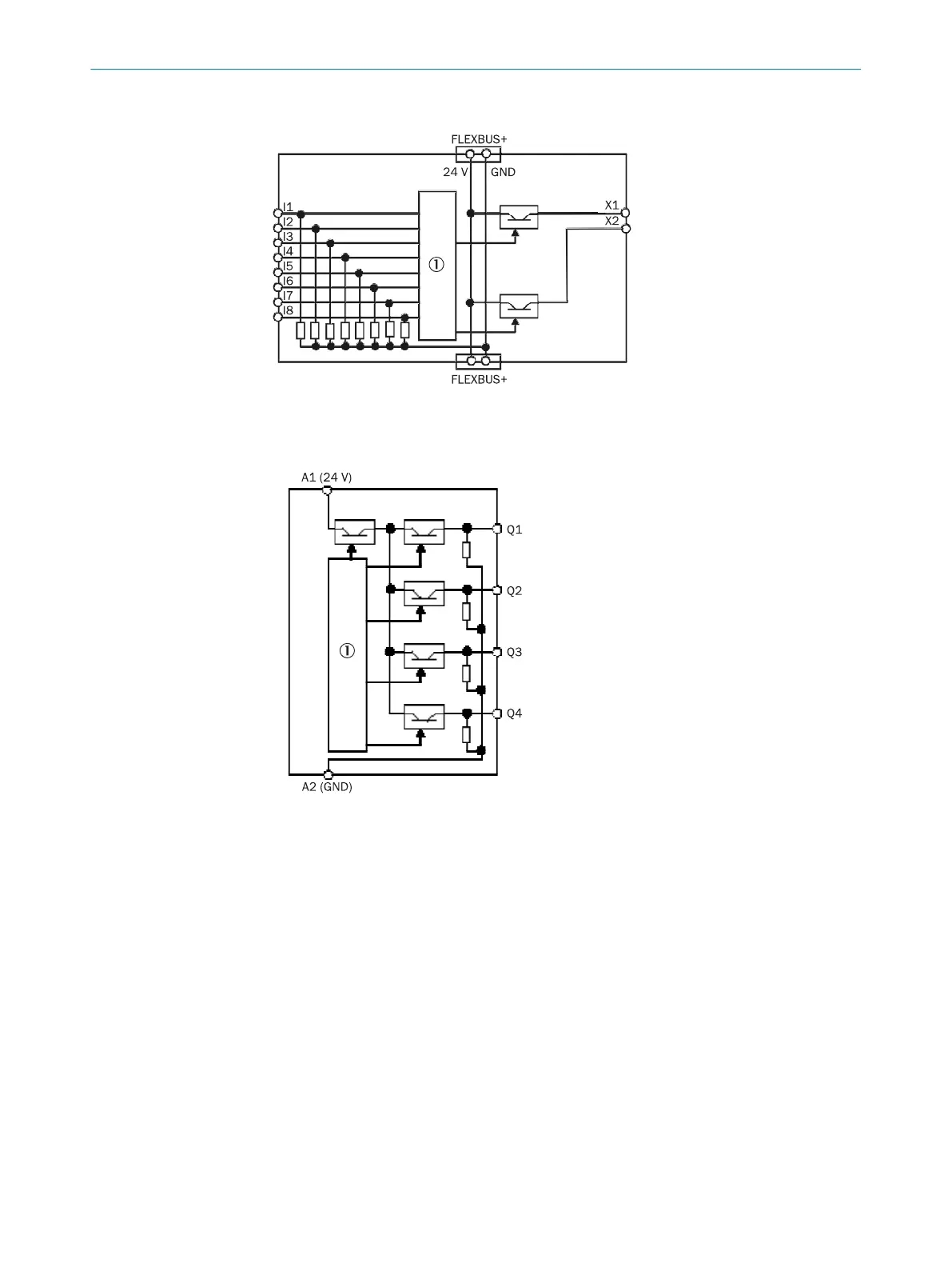
Figure 8: Internal structure of the FX3-XTIO – safety inputs and test outputs
1
Internal logic
Figure 9: Internal structure of the FX3-XTIO – safety outputs
1
Internal logic
3.4.6.2 Deactivation of test signals at outputs Q1 to Q4 on the FX3-XTIO
With the FX3-XTIO Step ≥2.xx (firmware versions V2.00.0), it is possible to deactivate
t
he test pulses at one or more outputs of FX3-XTIO modules.
Deactivating the test pulses at one or more of the outputs (Q1 to Q4) of an FX3-XTIO
module reduces the safety parameters of all the outputs (Q1 to Q4) of the module
concerned. If the test pulses are deactivated, a short-circuit cannot be recognized after
24V if the output is high. Therefore, in the case of a recognized internal hardware error,
the switch-off capability of the other outputs can be impaired by the reverse current of
24V via the output whose test pulse has been deactivated. This must be taken into
account to ensure that the application is in line with an appropriate risk analysis and
risk avoidance strategy.
3 P
RODUCT DESCRIPTION
26
O P E R A T I N G I N S T R U C T I O N S | Flexi Soft Modular Safety Controller 8012478/1IG6/2023-02-24 | SICK
Subject to change without notice