WARNING
R
educed safety parameters by deactivating test pulses
The target safety-related level may not be achieved in the event of non-compliance.
If the test pulse is deactivated at one or several of safety outputs Q1 to Q4, take the
following measures:
►
Use protected or separate cabling.
►
At least once a year, either switch off all outputs without test pulses simultane‐
ously for at least one second using the logic program of the main module or
restart the Flexi Soft system by switching off the voltage supply.
3.4.6.3 Extended error detection time for cross-circuits at outputs Q1 to Q4 on the FX3-XTIO for the
s
witching of increased capacitive loads
WARNING
Ext
ended error recognition time due to switching of higher capacitive loads
The target safety-related level may not be achieved in the event of non-compliance.
►
Pay attention to the extended error recognition time.
With the FX3-XTIO Step ≥3.xx (firmware version V3.00.0), it is possible to configure an
e
xtended fault detection time for cross-circuits that affect outputs Q1 to Q4 of FX3-XTIO
modules.
This may be necessary to switch loads where the voltage at the load does not drop to
the Low level as quickly as expected, with the result that if the standard error detection
time is set, a cross-circuit error occurs immediately after switching off (change from
High to Low). Examples of such instances include:
•
Loads with a capacitance that is higher than the standard level permitted for the
output,such as the supply voltage of PLC output cards that require safety-related
switching.
For this application, the test signal for the input must also be deactivated (see
"D
eactivation of test signals at outputs Q1 to Q4 on the FX3-XTIO", page 26).
Safety-capable inputs on fail-safe PLCs generally also have capacitance at the
inputs.
•
Induc
tive loads which cause an overshoot in the positive voltage range after the
induction voltage has died down.
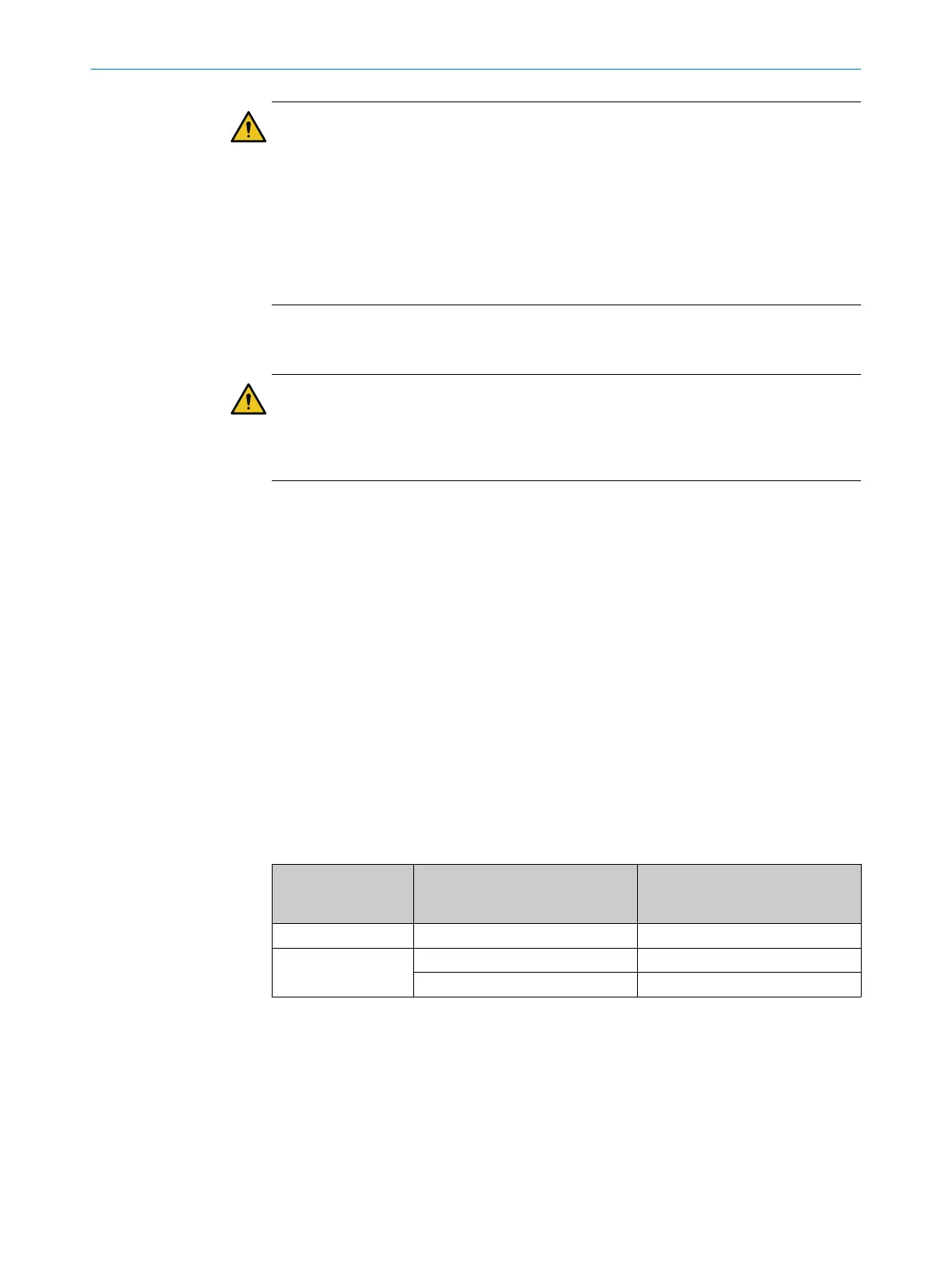
Table 6: Maximum permissible time until Low level is reached after output (Q1 to Q4) is deacti‐
vated
FX3-XTIO firmware
v
ersion
Switching of increased capacitive
loads
Maximum permissible time until
Low level (≤3.5V) is reached after
output (Q1 to Q4) is deactivated
≤ V2.11.0 Not possible 3 ms
≥ V3.00.0 Deactivated 3 ms
Activated 43 ms
Once the output has been deactivated, the capacitance that exceeds the standard
v
alue permitted for the output must be discharged by the user until the Low level is
reached. If this condition is not met within the maximum permissible time, it results in
a cross-circuit fault at the corresponding output regardless of whether test pulses are
activated or deactivated for the output concerned.
PRODUCT DESCRIPTION 3
8012478/1IG6/2023-02-24 | SICK O P E R A T I N G I N S T R U C T I O N S | Flexi Soft Modular Safety Controller
27
Subject to change without notice