Open
end
Micro D-sub
male c
onnector
of the FX3-
MOCx
Wiring
1)
Wire
c
olor
PI
N
Designa‐
tion
Sine/Cosine
encoder
A/B incremental encoder SSI
encoder
2output
pairs
(HTL24V,
HTL12V,
TTL)
2outputs
(HTL24V,
HTL12V,
TTL)
2output
pairs
(RS-422)
Violet 15 ENC2_A– Cos– Cos_Ref A– GND – Data–
Gray/
pink
7 ENC2_B+ Sin+ Sin B+ B – –
Red/
blue
14 ENC2_B– Sin– Sin_Ref B– GND – –
White/
gr
een
6 ENC2_C+ – – – – – Clock+
Brown/
green
13 ENC2_C– – – – – – Clock -
Voltage supply
Blue 4 ENC1_24V 24V voltage supply for encoder 1
Red 5 ENC2_24V 24V voltage supply for encoder 2
White/
y
ellow
12 ENC_0V GND connection for encoder 1 and 2
1)
A combination of different encoder types is possible.
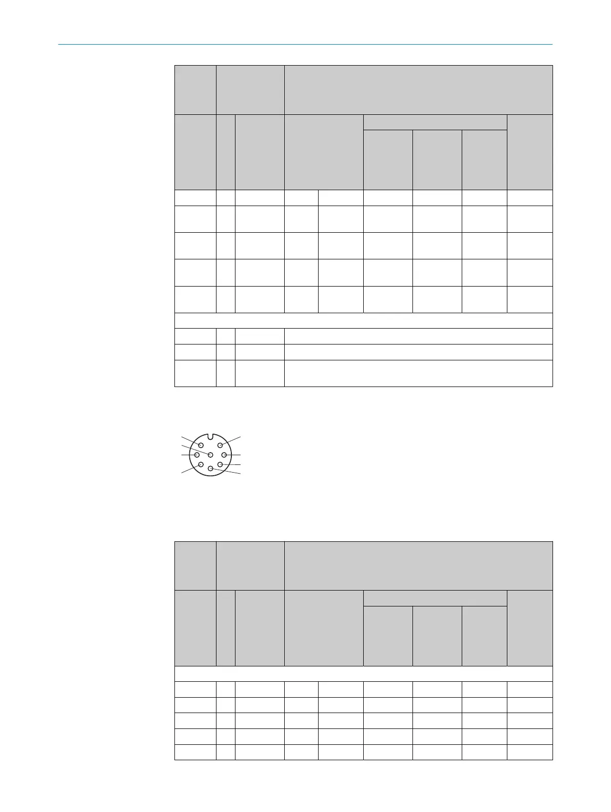
Y-connecting cable for directly connecting two encoders
Figure 39: M12 female connector, 8-pin
C
onnecting cables with material numbers and dimensions, see table 203, page 184
Table 42: Y-connecting cable for directly connecting two encoders
2× M12,
f
emale
connec‐
tor, 8-pin
Micro D-sub
male connector
of the FX3-
MOCx
Wiring
1)
PIN PI
N
Designa‐
tion
Sine/Cosine
encoder
A/B incremental encoder SSI
encoder
2)
2output
pair
s
(HTL24V,
HTL12V,
TTL)
2)
2outputs
(HTL24V,
HTL12V,
TTL)
2)
2output
pairs
(RS-422)
Encoder 1
1 9 ENC1_A– Cos– Cos_Ref A– GND – Data–
2 1 ENC1_A+ Cos+ Cos A+ A – Data+
3 10 ENC1_B– Sin– Sin_Ref B– GND – –
4 2 ENC1_B+ Sin+ Sin B+ B – –
5 3 ENC1_C+ – – – – – Clock+
ELECTRICAL INSTALLATION 5
8012478/1IG6/2023-02-24 | SICK O P E R A T I N G I N S T R U C T I O N S | Flexi Soft Modular Safety Controller
71
Subject to change without notice