2× M12,
f
emale
connec‐
tor, 8-pin
Micro D-sub
male connector
of the FX3-
MOCx
Wiring
1)
PIN PI
N
Designa‐
t
ion
Sine/Cosine
encoder
A/B incremental encoder SSI
encoder
2)
2output
pairs
(HTL24V,
HTL12V,
TTL)
2)
2outputs
(HTL24V,
HTL12V,
TTL)
2)
2output
pairs
(RS-422)
6 11 ENC1_C– – – – – – Clock -
7 12 ENC_0V GND connection for encoder 1
8 4 ENC1_24V 24V voltage supply for encoder 1
Encoder 2
1 15 ENC2_A– Cos– Cos_Ref A– GND – Data–
2 8 ENC2_A+ Cos+ Cos A+ A – Data+
3 14 ENC2_B– Sin– Sin_Ref B– GND – –
4 7 ENC2_B+ Sin+ Sin B+ B – –
5 6 ENC2_C+ – – – – – Clock+
6 13 ENC2_C– – – – – – Clock -
7 12 ENC_0V GND connection for encoder 2
8 5 ENC2_24V 24V voltage supply for encoder 2
1)
A combination of different encoder types is possible.
2)
Consider possible measures for common cause errors. See "Mo
tion Control FX3-MOC0", page 34 or
"Motion Control FX3-MOC1", page 36.
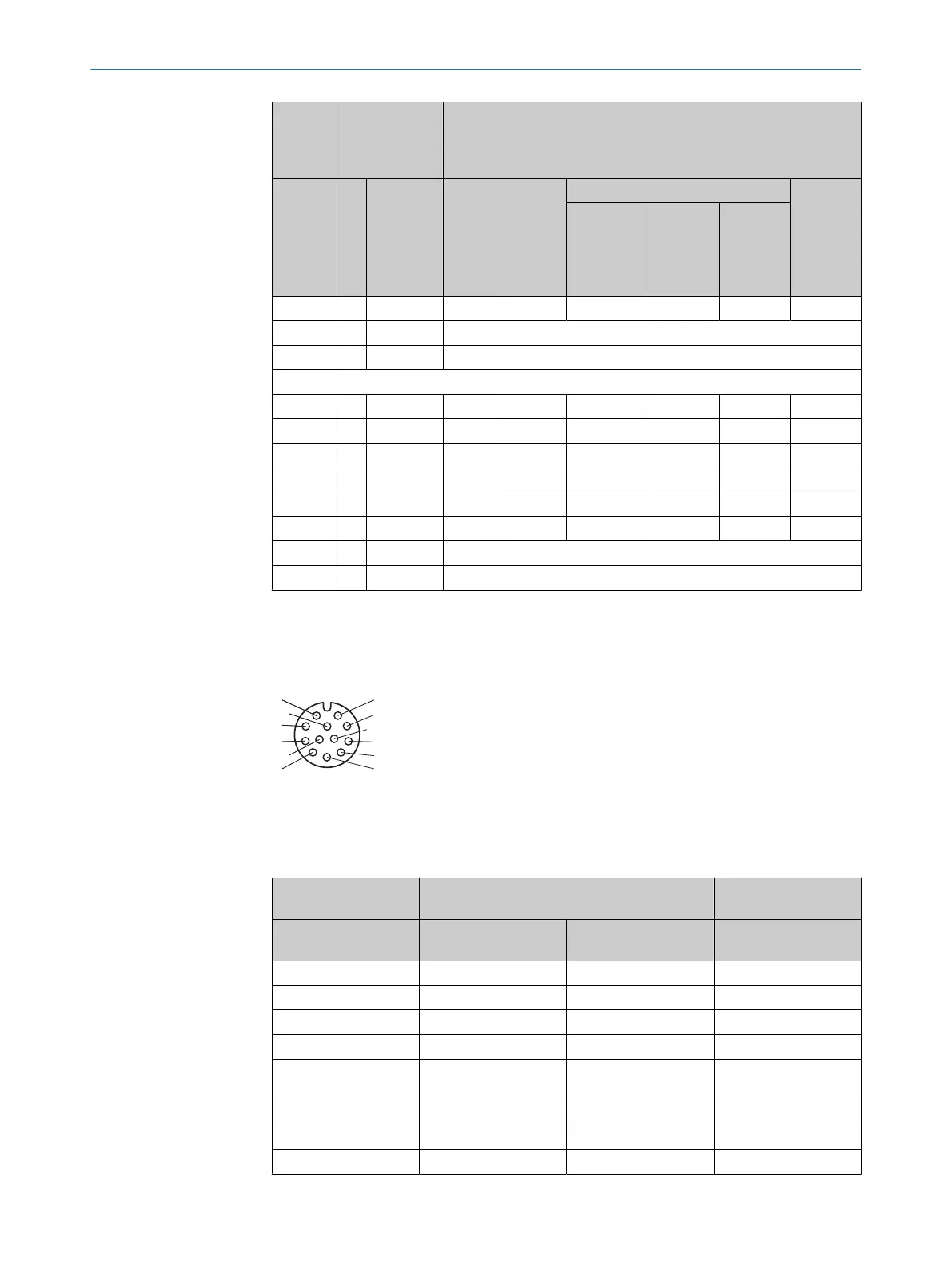
Connecting cable for direct connection of the AFS/AFM60Spro safety encoder
Figure 40: Female connector, M12, 12-pin
Connecting cables with material numbers and dimensions, see table 201, page 183
Table 43: Connecting cable for direct connection of the AFS/AFM60Spro safety encoder
1× M12, female con‐
nec
tor, 12-pin
Micro D-sub male connector of the FX3-MOCx Wiring
PIN PIN Designation SSI + Sin/Cos
encoder
1 – – –
2 1 ENC1_A+ Data+
3 9 ENC1_A– Data–
4 11 ENC1_C– Clock–
5 4 ENC1_24V 24V voltage supply for
encoder
6 8 ENC2_A+ Cos+
7 15 ENC2_A– Cos–
8 7 ENC2_B+ Sin+
5 ELECTRICAL INSTALLATION
72
O P E R A T I N G I N S T R U C T I O N S | Flexi Soft Modular Safety Controller 8012478/1IG6/2023-02-24 | SICK
Subject to change without notice