Chapter 11 Operating Instructions
M4000 Adv., Adv. A/P, Area
74 © SICK AG • Industrial Safety Systems • Germany • All rights reserved 8010797/PA53/27-06-05
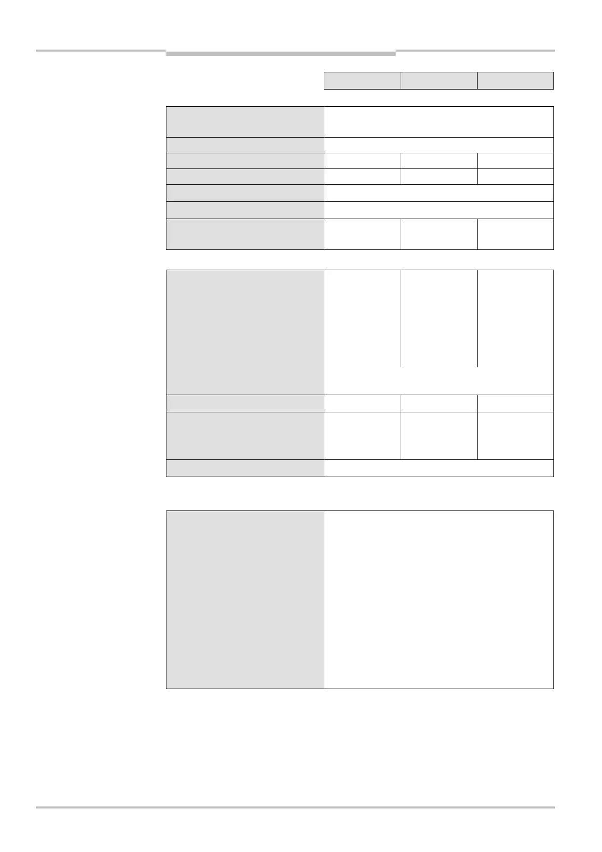
Technical specifications
Minimum Typical Maximum
Protection class
(EN 50178:1998)
4)
III
Enclosure rating (IEC 60529) IP 65
Supply voltage V
S
at device
5)
19.2 V 24 V 28.8 V
Residual ripple
6)
±10%
Synchronisation
7)
Optical, without separate synchronisation
Type acc. to IEC 61496 Type 4
Power-up delay of sender and
receiver before ready
10 s
Sender
Test input
Input voltage
8)
HIGH (active) 11 V 24 V 30 V
Input current HIGH 7 mA 10 mA 20 mA
Switching voltage LOW
(inactive)
–30 V 0 V 5 V
Input current LOW
8)
–3.5 mA 0 mA 0.5 mA
Response time to test Depending on the number of beams, maximum
150 ms
Wavelength of sender
7)
950 nm
Power consumption
M4000 Advanced,
M4000 Area 60/80
0.2 A
Weight, type-dependent See section 11.2 “Table of weights” on page 78ff.
Receiver or
M4000 Advanced A/P
Output signal switching devices
(OSSDs)
2 PNP semiconductors, short-circuit protected
9)
,
cross-circuit monitored
Response time
M4000 Advanced,
M4000 Advanced A/P
2 to 6 beams 10 ms
7 to 11 beams 11 ms
12 beams 12 ms
M4000 Area 60/80
Non-coded 11 ms
Coded 17 ms
4)
Safety extra-low voltage SELV/PELV.
5)
The external voltage supply must be capable of buffering brief mains voltage failures of 20 ms as specified in
EN 60204-1. Suitable power supplies are available as accessories from SICK (Siemens type series 6 EP 1).
6)
Within the limits of V
S
.
7)
Only with Active/Active systems.
8)
As per IEC 61131-2.
9)
Applies to the voltage range between –30 V and +30 V.
AUDIN - 7 bis rue de Tinqueux - 51100 Reims - France - Tel : 03.26.04.20.21 - Fax : 03.26.04.28.20 - Web : http: www.audin.fr - Email : info@audin.fr

 Loading...


