Operating Instructions Chapter 11
M4000 Adv., Adv. A/P, Area
8010797/PA53/27-06-05 © SICK AG • Industrial Safety Systems • Germany • All rights reserved
75
Technical specifications
Minimum Typical Maximum
Switch off time 100 ms
Power-up delay 6.5 × response
time
Switching voltage
10)
11)
HIGH
(active, U
eff
)
V
s
– 2.25 V 24 V V
s
Switching voltage
LOW (inactive) 0 V0 V3.5 V
Switching current 0 mA 500 mA
Leakage current
12)
0.25 mA
Load capacity 2.2 µF
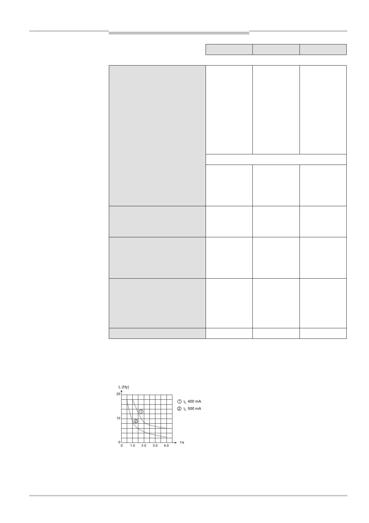
Switching sequence Depending on load inductance
Load inductance
13)
2.2 H
Test pulse data
14)
Test pulse width 120 µs 150 µs 300 µs
Test pulse rate 3
1
/s 5
1
/s 10
1
/s
Permissible cable resistance
Between device and load
15)
2.5
Supply lead 1
Power consumption
M4000 Advanced 0.7 A
16)
M4000 Advanced A/P 0.7 A
16)
M4000 Area 60/80 0.7 A
16)
External device monitoring (EDM)
input
Input voltage
17)
HIGH (inactive) 11 V 24 V 30 V
Input current HIGH 6 mA 10 mA 20 mA
Input voltage
17)
LOW (active) –30 V 0 V 5 V
Input current LOW –2.5 mA 0 mA 0.5 mA
10)
As per IEC 61131-2.
11)
On the device plug.
12)
In the case of a fault (0-V cable open circuit) maximally the leakage current flows in the OSSD cable. The
downstream controller must detect this status as LOW. A FPLC (fail-safe programmable logic controller) must
be able to identify this status.
13)
The maximum rated load inductance is higher with lower switching sequence.
14)
When active, the outputs are tested cyclically (brief LOW). When selecting the downstream controllers, make
sure that the test pulses do not result in deactivation when using the above parameters.
15)
Make sure to limit the individual cable resistance to the downstream controller to this value to ensure that a
cross-circuit between the outputs is safely detected. (Also note EN 60204 Electrical Machine Equipment, Part
1: General Requirements.)
16)
Without OSSDs, without ADO, without Reset required and without UE403.
17)
As per IEC 61131-2.
AUDIN - 7 bis rue de Tinqueux - 51100 Reims - France - Tel : 03.26.04.20.21 - Fax : 03.26.04.28.20 - Web : http: www.audin.fr - Email : info@audin.fr

 Loading...


