Chapter 5 Operating Instructions
M4000 Adv., Adv. A/P, Area
40 © SICK AG • Industrial Safety Systems • Germany • All rights reserved 8010797/YT72/2016-02-19
Subject to change without notice
Configurable functions
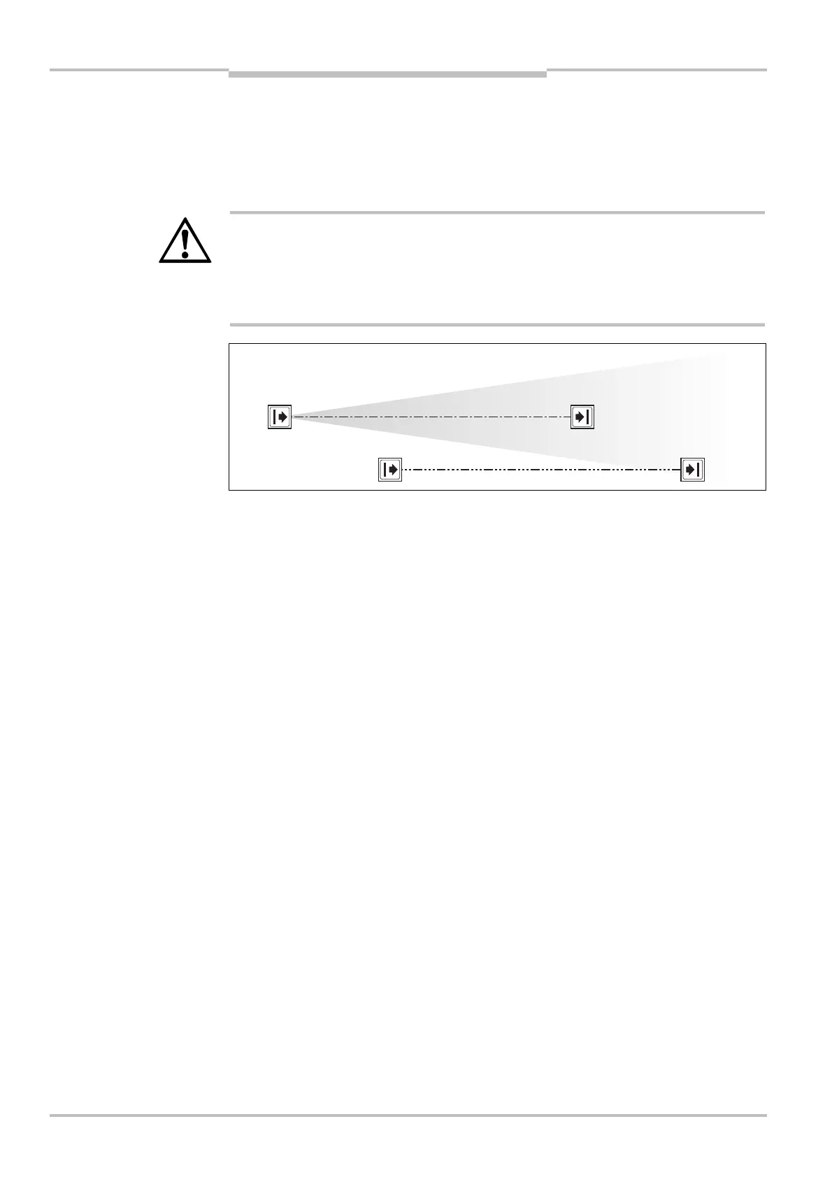
5.2 Beam coding
I
f several multiple light beam safety devices operate in close proximity to each other, the
sender beams of one system may interfere with the receiver of another system. With
code 1 or 2 activated, the receiver can distinguish the beams designated for it from other
beams. The following settings are available: non-coded, code 1 and code 2.
WARNING
Use different beam codings if the systems are mounted in close proximity!
Systems mounted in close proximity to each other must be operated with different beam
codings (code 1 or code 2). If this precaution is neglected, the system may be impaired in
its protective function by the beams from the neighbouring system and so change to the
unsafe state. This would mean that the operator is at risk.
Beam coding increases the availability of the protected machine. Beam coding also
enhances the resistance to optical interference such as weld sparks or similar.
Within a system you must configure the beam coding for every device (sender and
receiver) separately.
After switching on, the 7Esegment display of sender and receiver will briefly display the
coding.
Device symbol M4000 Advanced (sender or receiver), M4000 Advanced (A/P) or M4000
Area (sender or receiver), context menu Open device window, parameter node General.
Fig. 25: Schematic
illustration of the beam
coding
Notes