Operating Instructions Chapter 7
M4000 Adv., Adv. A/P, Area
8010797/YT72/2016-02-19 © SICK AG • Industrial Safety Systems • Germany • All rights reserved 69
Subject to change without notice
Mounting
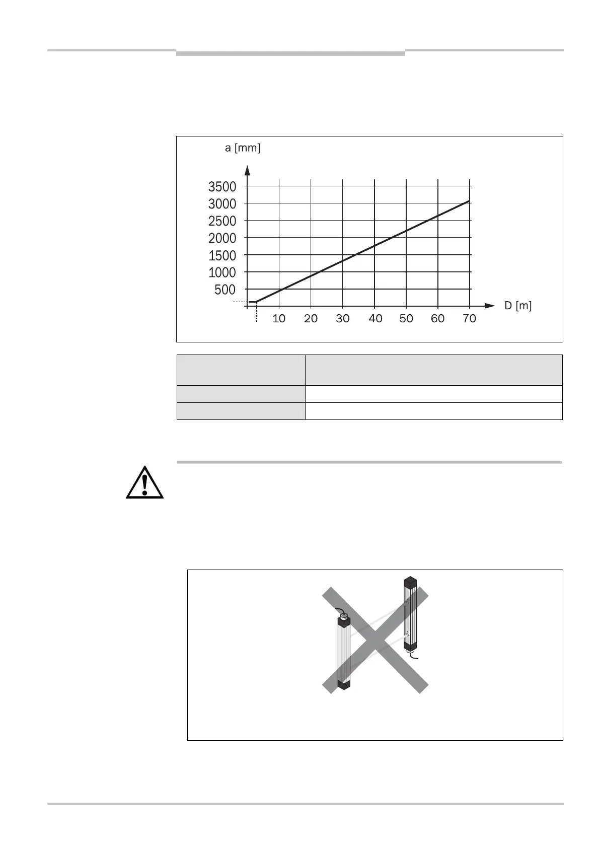
How to determine the minimum distance from reflective surfaces:
Determine the distance D [m] sender–receiver.
Read the minimum distance a [mm] in the diagram or calculate it using the related
formula in Tab. 30.
Distance D [m]
sender–receiver
Calculation of the minimum distance a from reflective
surfaces
D 3 m a [mm] = 131
D > 3 m a [mm] = tan(2.5°) × 1000 × D [m] = 43.66 × D [m]
7.2 Steps for mounting the device
WARNING
Special features to note during mounting:
Always mount the sender and receiver parallel to one another.
During mounting, ensure that sender and receiver are aligned correctly. The optical lens
systems of sender and receiver must be located in exact opposition to each other; the
status indicators must be mounted at the same height. The system plugs of both de-
vices must point in the same direction.
Fig. 38: Graph, minimum
distance from reflective
surfaces
calculation of the minimum
distance to reflective
surfaces
Fig. 39: Sender and receiver
must not be rotated 180°
with respect to each other

 Loading...


