Operating Instructions Chapter 8
M4000 Adv., Adv. A/P, Area
8010797/YT72/2016-02-19 © SICK AG • Industrial Safety Systems • Germany • All rights reserved 83
Subject to change without notice
Electrical installation
mend — especially when using the combination M4000 Advanced or M4000 Ad-
vanced A/P with the UE403 safety relay at the extension connection — the termination
of the connections pin 9 and 10 (EFI device communication) on the system connection
in the control cabinet using a resistor of 182 (SICK part number 2027227). Alter-
natively we recommend the use of a connecting cable on which pin 9 and 10 are not
used(see section 14.7 “Accessories” on page 139).
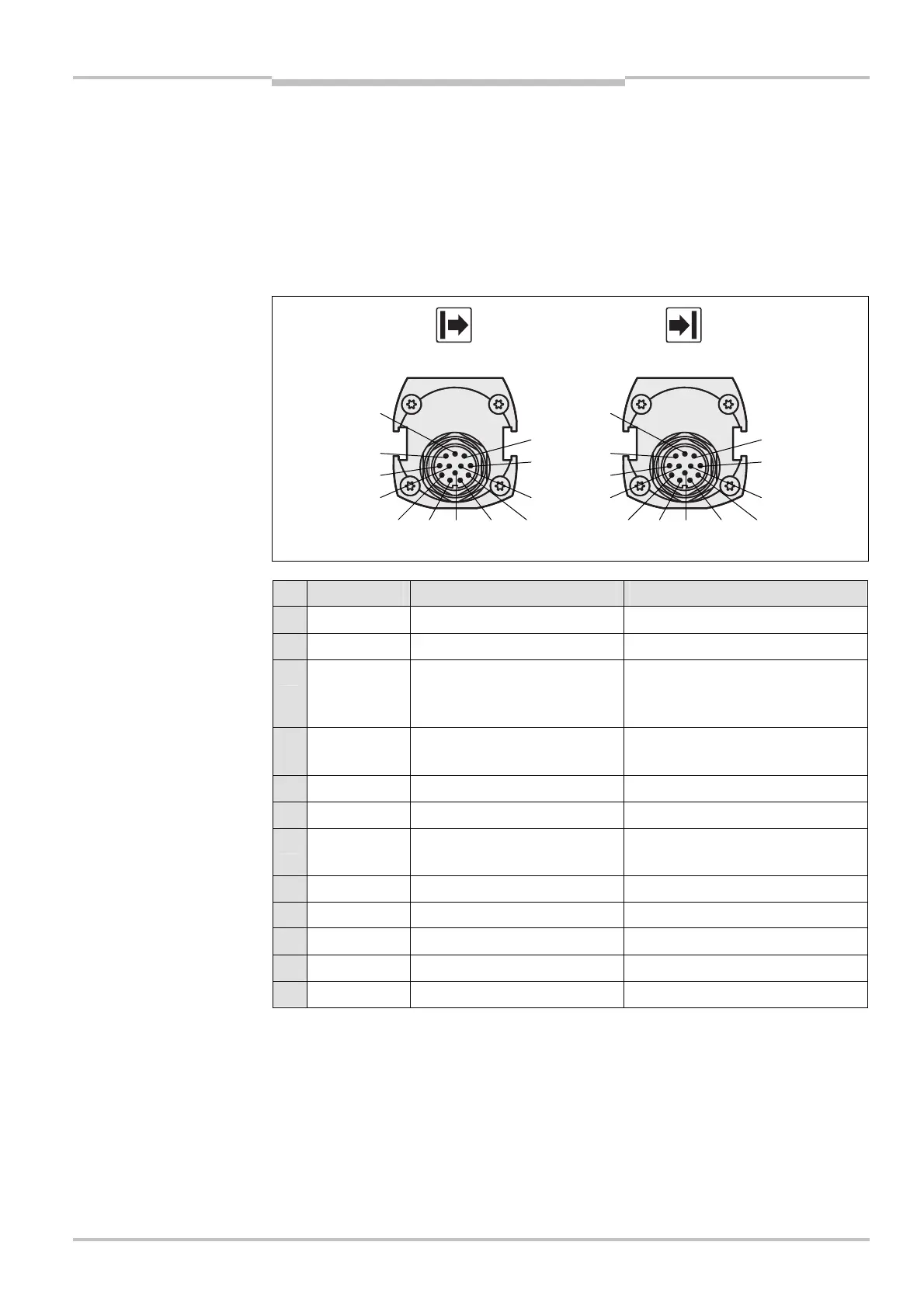
8.1.2 M4000 Area 60/80
Pin Wire colour Sender Receiver
1 Brown Input 24 V DC (voltage supply) Input 24 V DC (voltage supply)
2 Blue 0 V DC (voltage supply) 0 V DC (voltage supply)
3 Grey Test input:
0 V: external test active
24 V: external test inactive
OSSD1 (output signal switching
device 1)
4 Pink Reserved OSSD2 (output signal switching
device 2)
5 Red Reserved Reset/restart
6 Yellow Reserved External device monitoring (EDM)
7 White Reserved Application diagnostic output
(ADO)
8 Red/blue Reserved Reset required
9 Black Device communication (EFI
A
) Device communication (EFI
A
)
10 Purple Device communication (EFI
B
) Device communication (EFI
B
)
11 Grey/pink Reserved Reserved
FE Green Functional earth Functional earth
For the connection of pin 9 and 10 only use cable with twisted cores, e.g. the SICK con-
nection cables available as accessories (see section 14.7 “Accessories” on page 139).
If you do not use either a UE403 or a sens:Control device on the system connection
pin 9 and 10 (EFI device communication), to improve the EMC behaviour we recom-
mend the termination of the connections pin 9 and 10 (EFI device communication) on
the system connection in the control cabinet using a resistor of 182 (SICK part num-
ber 2027227). Alternatively we recommend the use of a connecting cable on which
pin 9 and 10 are not used (see section 14.7 “Accessories” on page 139).
Fig. 52: Pin assignment
system connection M4000
Area 60/80 M26
× 11 + FE
system connection M4000
Area 60/80 M26
× 11 + FE
Notes