Chapter 7 Operating Instructions
M4000 Adv., Adv. A/P, Area
68 © SICK AG • Industrial Safety Systems • Germany • All rights reserved 8010797/YT72/2016-02-19
Subject to change without notice
Mounting
Approach Calculation Conditions
Parallel S = 1600 × T + (1200 – 0.4 × H)
[mm]
1200 – 0.4 × H > 850 mm
15 × (d – 50) H 1000 mm
Angular > 30° calculation as for
perpendicular approach
< 30° calculation as for
parallel approach
S is applied to the beam that is the
farthest away from the hazardous
point.
d H
min
/15 + 50
H
max
1000 mm
Where …
S = Minimum distance [mm]
H = Height of the beams above the floor [mm]
For approach at an angle:
H
max
= Height of the uppermost beam [mm]
H
min
= Height of the bottom beam [mm]
d = Resolution of the multiple light beam safety device [mm]
= Angle between detection plane and the direction of entry
T = Time
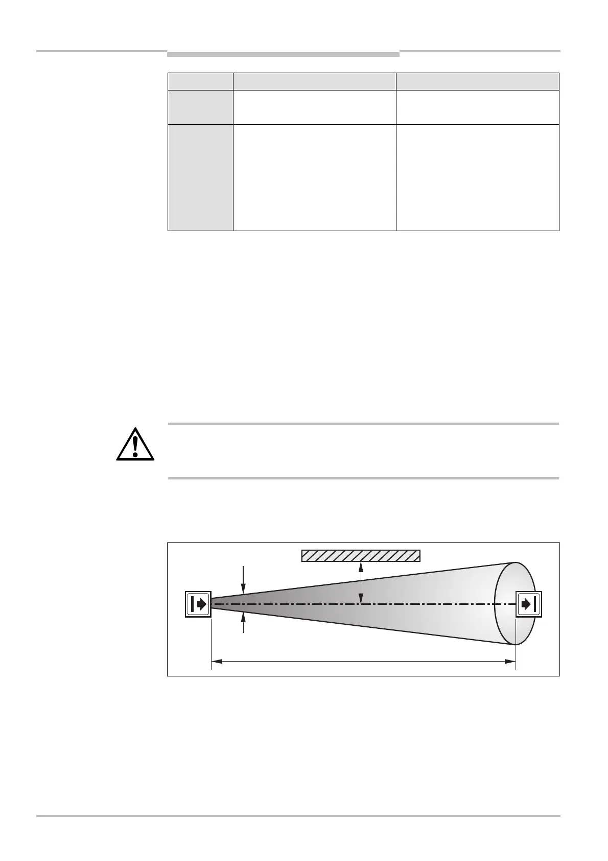
7.1.2 Minimum distance to reflective surfaces
WARNING
Maintain the minimum distance from reflective surfaces!
The light beams from the sender may be deflected by reflective surfaces. This can result in
failure to identify an object. This would mean that the operator is at risk.
All reflective surfaces and objects (e.g. material bins) must be a minimum distance a from
the light path between sender and receiver. The minimum distance a depends on the
distance D between sender and receiver.
The field of view of the sender and receiver optics is identical.
calculating the minimum
distance S
Fig. 37: Minimum distance to
reflective surfaces
Note