Operating Instructions Chapter 7
M4000 Adv., Adv. A/P, Area
8010797/YT72/2016-02-19 © SICK AG • Industrial Safety Systems • Germany • All rights reserved 67
Subject to change without notice
Mounting
How to calculate the minimum distance D
s
according to ANSI B11.19:2003G04,
Annex D and Code of Federal Regulations, Volume 29, Part 1910.217 … (h) (9) (v):
T
he following calculation shows an example calculation of the minimum distance.
Depending on the application and the ambient conditions, a different calculation may be
necessary.
First, calculate D
s
using the following formula:
D
s
= H
s
× (T
s
+ T
c
+ T
r
+ T
bm
) + D
pf
Where …
D
s
= The minimum distance in inches (or millimetres) from the hazardous point to the
protective device
H
s
= A parameter in inches/second or millimetres/second, derived from data on
approach speeds of the body or parts of the body.
Often 63 inches/second is used for H
S
.
T
s
= Stopping/run down time of the machine tool measured at the final control
element
T
c
= Stopping/run-down time of the control system
T
r
= Response time of the entire protective device after light path interruption
T
bm
= Additional response time allowed for brake monitor to compensate for wear
Any additional response times must be accounted for in this calculation.
D
pf
= An additional distance added to the overall minimum distance required. This
value is based on a possible intrusion toward the hazardous point prior to actu-
ation of the electro-sensitive protective equipment (ESPE). For applications that
can be reached over, the value D
p
f
= 1.2 m. For beam arrangements that permit
reaching in with the arms or the detectable object size is greater than 63 mm,
the value D
pf
= 0.9 m.
The applicable legal and official regulations apply to the use and mounting of the protec-
tive device. These regulations vary depending on the application.
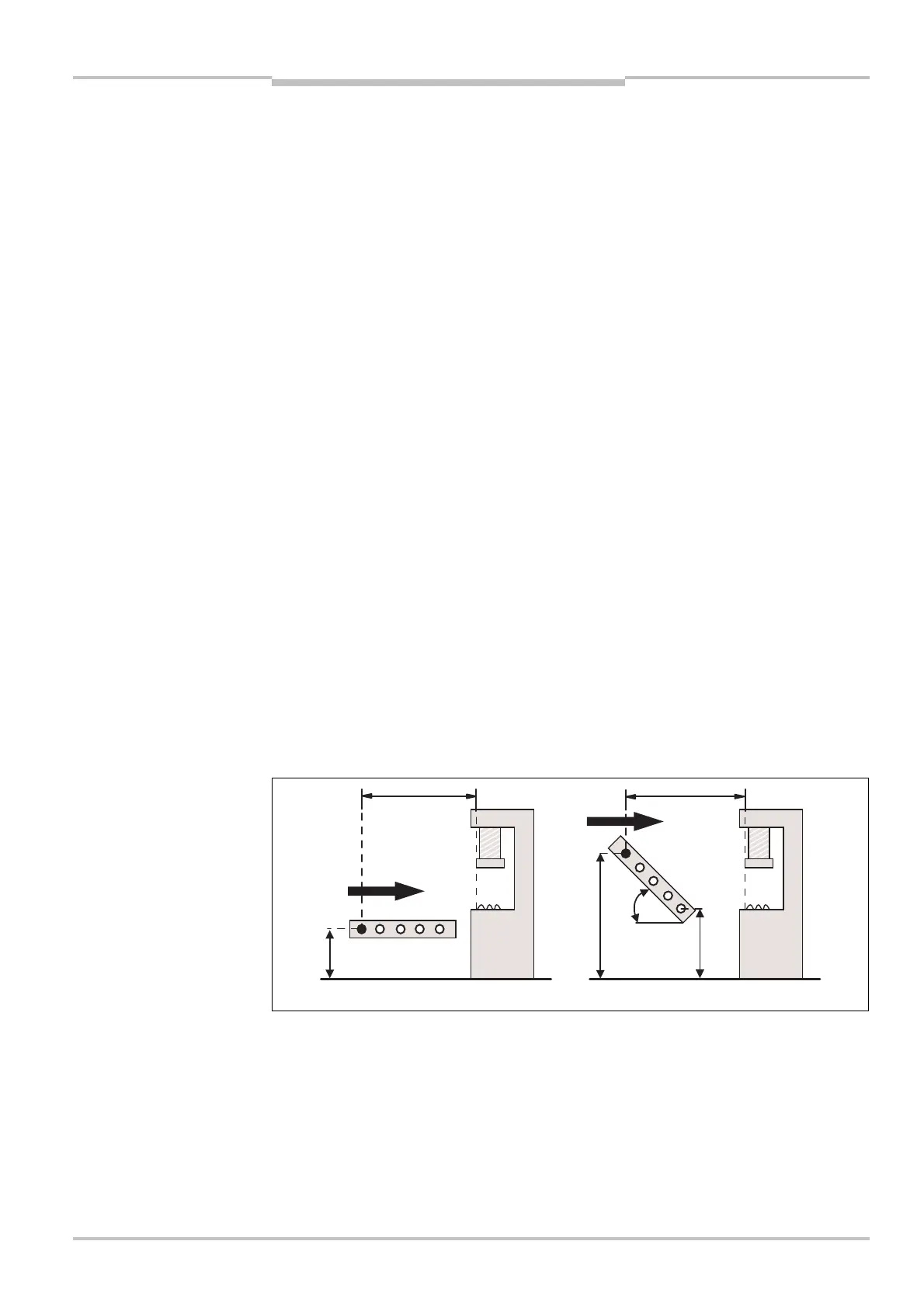
Calculation of the minimum distance S for non-perpendicular approach
Note
Note
Fig. 36: Minimum distance to
the hazardous point for non-
perpendicular approach
min
max
approach