Chapter 13 Operating Instructions
M4000 Adv., Adv. A/P, Area
120 © SICK AG • Industrial Safety Systems • Germany • All rights reserved 8010797/YT72/2016-02-19
Subject to change without notice
Technical specifications
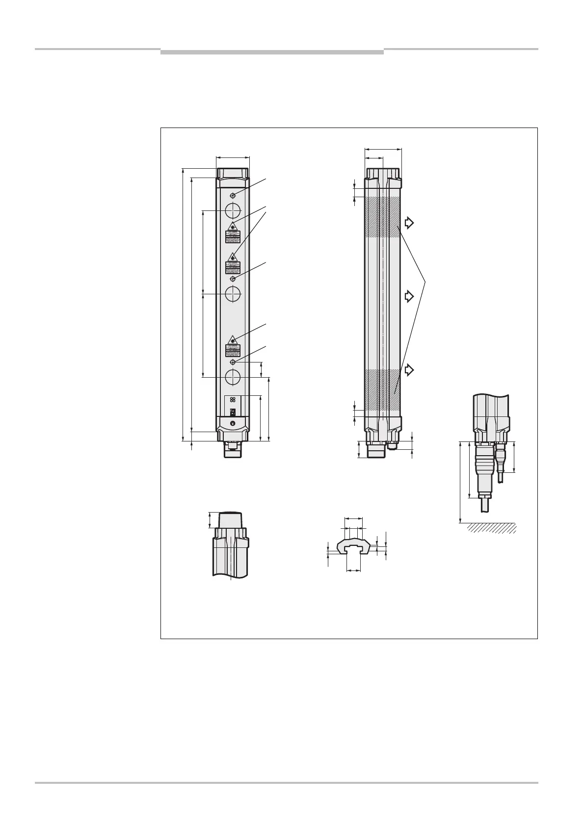
13.3 Dimensional drawings
13.3.1 M4000 Advanced, M4000 Advanced A/P
Fig. 69: Dimensional drawing
M4000 Advanced receiver
(sender mirror image) or
M4000 Advanced A/P (mm)
(receiver with
integrated alignment
aid only)
(receiver with
integrated alignment
aid only)
Optional (receiver only):
Design with integrated
LED
side mounting
contacts (for DIN 43
and cable plug M12 with
cable (right, only on receiver)
87
47.5
brackets
M4000 Advanced A/P

 Loading...


