Operating Instructions Chapter 3
M4000 Adv., Adv. A/P, Area
8010797/YT72/2016-02-19 © SICK AG • Industrial Safety Systems • Germany • All rights reserved 19
Subject to change without notice
Product description
3.4 Controls and status indicators
T
he LEDs and the 7Esegment display of sender and receiver signal the operating status of
the M4000.
The depiction of numbers on the 7E segment display can be rotated by 180° with the aid of
the CDS (Configuration & Diagnostic Software). If you rotate the numbers of the 7Esegment
display, the point in the 7Esegment display goes out:
Point visible: The bottom edge of the numbers on the 7Esegment display is pointing
towards the configuration connection.
Point not visible: The bottom edge of the numbers on the 7Esegment display is pointing
towards the LED display.
Device symbol M4000 Advanced (sender or receiver), M4000 Advanced (A/P) or M4000
Area (sender or receiver), context menu Open device window, parameter node General.
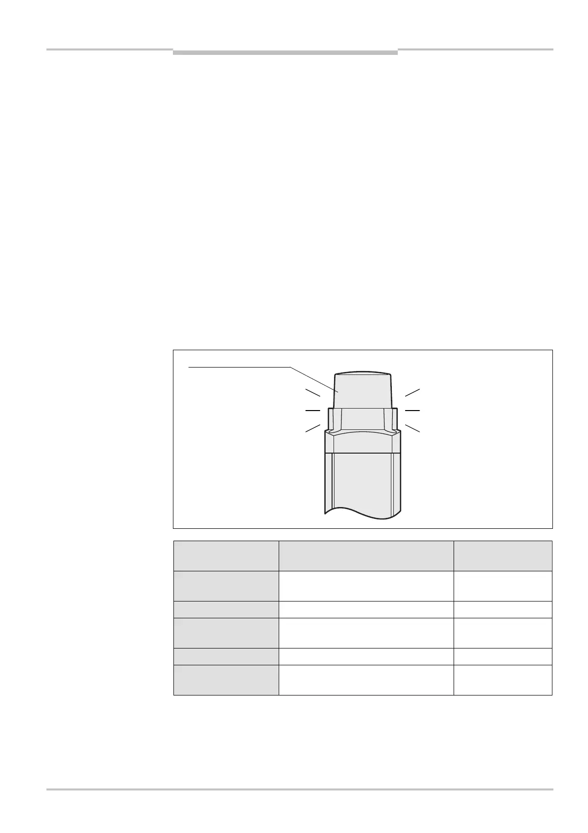
3.4.1 End cap with integrated LED (optional, only on receiver)
The end cap with integrated LED is available only for the receiver of the M4000 Ad-
vanced and the M4000 Advanced A/P.
The integrated LED is not monitored. This means that a failure of the integrated LED has
no effect on the function of the M4000.
Display Meaning Output signal
switching devices
Red System providing signals for shutting
down the machine
Off
Green System clear On
Yellow Muting
(only with UE403 or sens:Control)
On
Yellow/red (1 Hz) Reset required Off
Yellow/red (2 Hz) Override required
(only with UE403 or sens:Control)
Off
Note
Notes
Fig. 10: End cap with
integrated LED
indications on the integrated
LED
LED

 Loading...


