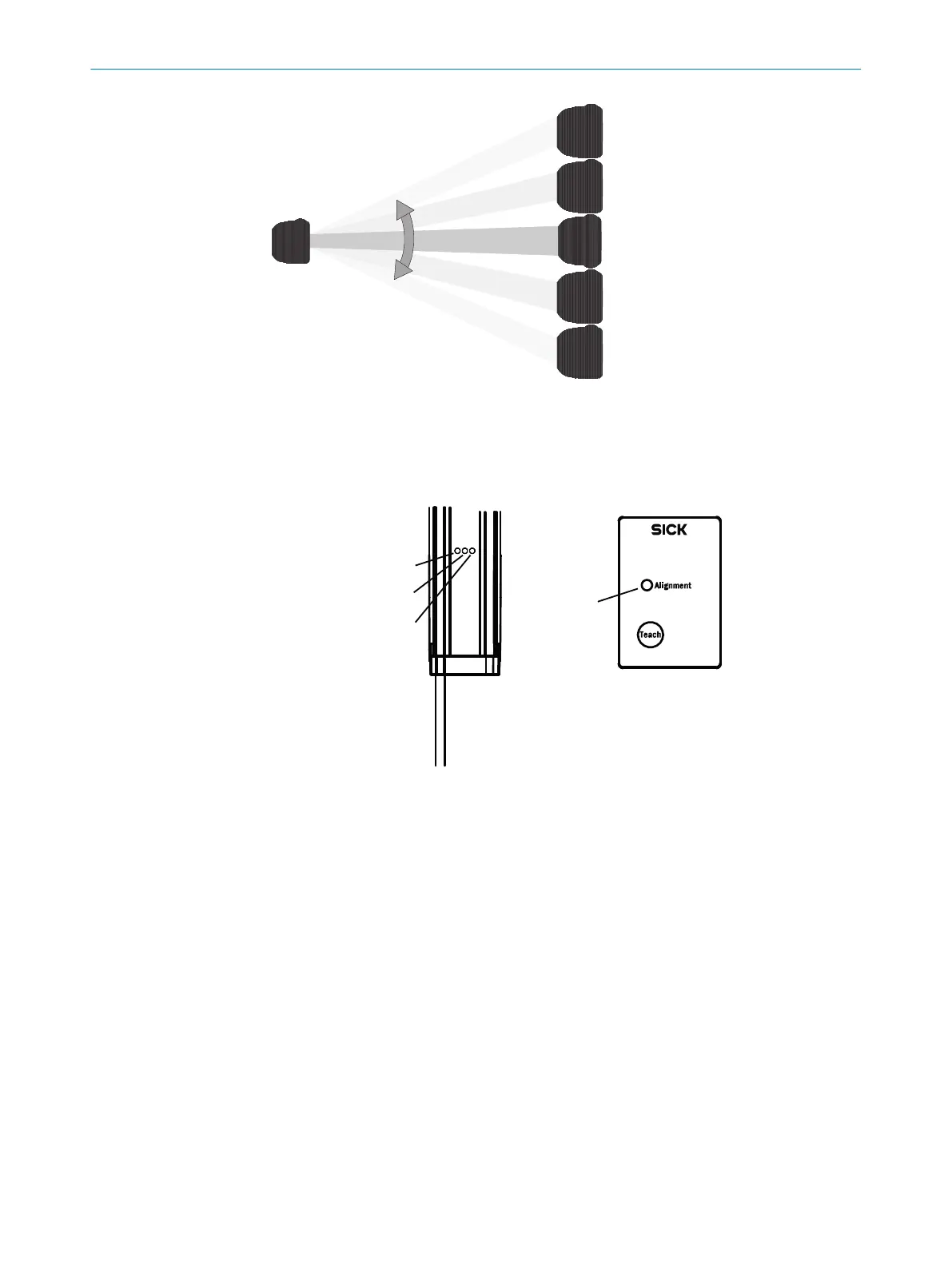
Figure 42: Rotate the receiver once
The yellow LED on the front of the receiver and the Alignment
LED show the rough align‐
ment.
Figure 43: Control panel
1
Yellow
2
Red
3
Green
4
Alignment LED
Ö 3 Hz yellow
T
he yellow LED on the front and the Alignment LED on the control panel flash quickly.
b
Improve the alignment of the MLG-2.
✓
When the yellow LED and the Alignment LED go out, the MLG-2 is optimally aligned.
b
Then use an M5 screw to fix the position of the sender and receiver.
5)
Teach-in
b
Pre
ss the Teach pushbutton (< 1 s).
6)
✓
Ö 1 Hz yellow
✓
The yellow LED on the front and the Alignment LED flash slowly.
5)
For ali
gnment, you can also use the installation assistant in SOPAS ET.
6)
Teach-in can also be initiated by SOPAS ET or the PLC.
8 OPERATING MLG-2 VIA CONTROL PANEL
52
O P E R A T I N G I N S T R U C T I O N S | MLG-2 WebChecker 8025190/2020-01-13 | SICK
Subject to change without notice