Digital Modules
3-104
Programmable Logic Controllers S7-300 Module Data
A5E00105505-03
3.29.1 SM 322; DO 8 x Rel. 230 VAC/5A parameterization
Parameter assignment
You will find the general procedure for assigning parameters to digital modules in
Section 3.3.
Parameters of the SM 322; DO 8 x Rel. 230 VAC/5A
You will find an overview of the parameters that you can set and their default
settings for the SM 322; DO 8 x 230 VDC/0.5 A in the table below.
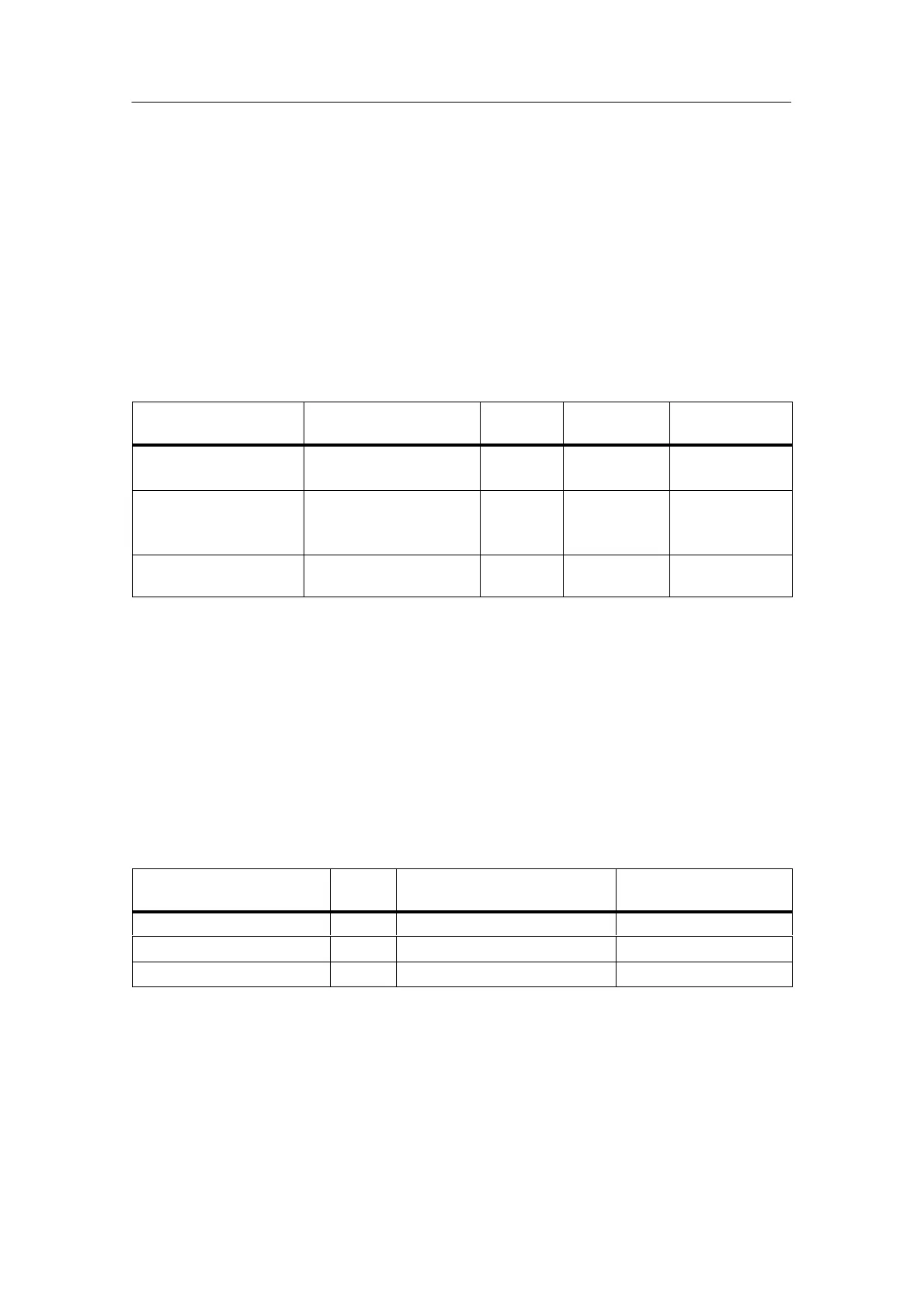
Table 3-25 Parameters of the SM 322; DO 8 x Rel. 230 VAC/5A
Parameter
Value Range Default
settings
Parameter
type
Scope
Enable
• Diagnostic interrupts Yes/no No Dynamic Module
Behavior on CPU STOP Switch substitute value
(EWS)
Hold last value (LWH)
EWS Dynamic Channel
Switch substitute value
“1”
Yes/no No Dynamic Channel
3.29.2 Behavior and Diagnostics of the SM 322; DO 8 x 230 VDC/0.5 A
Diagnostic messages of the SM 322; DO 8 x Rel. 230 VAC/5A
The table below presents an overview of the diagnostic messages for the
SM 322; DO 8 x Rel. 230 VAC/5 A.
Table 3-26 Diagnostic Messages of the SM 322; DO 8 x Rel. AC 230 VDC/0.5 A
Diagnostics message
LED Scope of the diagnostics Parameters can be
assigned
Time-out SF Module No
EPROM error SF Module No
RAM error SF Module No
 Loading...


