Analog Modules
4-113
Programmable Logic Controllers S7-300 Module Data
A5E00105505-03
4.21.1 Parameters of the SM 331; AI 8 x 13 bits
Parameter
You will find a description of the general procedure for assigning parameters to
analog modules in the reference manual, section 4.7.
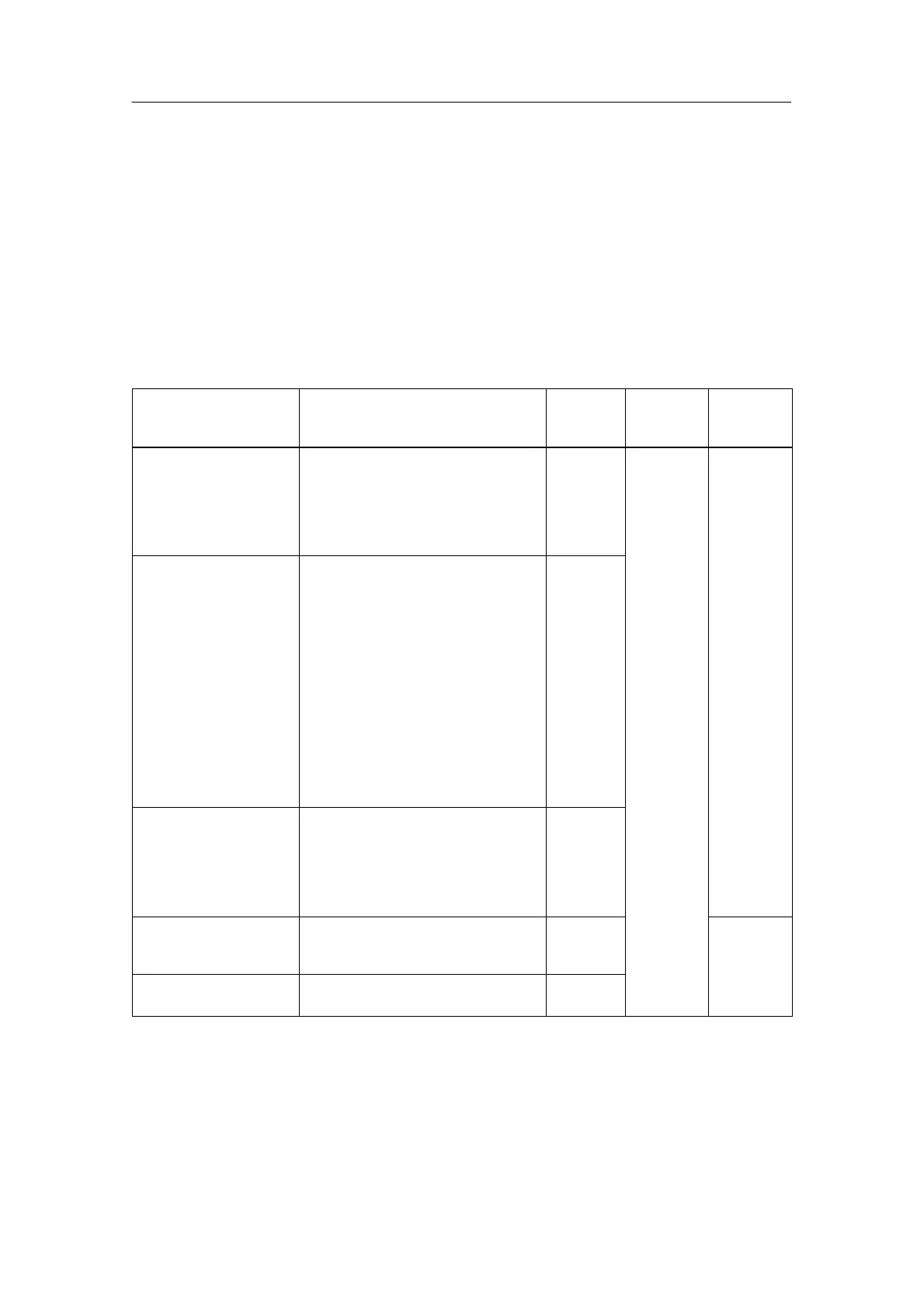
An overview of the parameters that you can set and their default settings are
shown in the table below.
Table 4-63 Parameters of the SM 331; AI 8 x 13 bits
Parameter
Value Range Default
Settings
Para-
meter
Type
Scope
Measurement
• Measuring Method Deactivated
U Voltage
I Current
R Resistors
RTD Bulb resistor
U
• Measuring Range Voltage
"50 mV; "500 mV; "1 V;
1 to 5 V;
"5 V; 0 to 10 V; "10 V
"10 V
Current
0 to 20 mA; 4 to 20 mA; "20 mA "20 mA
Resistors
0 to 600 Ω; 0 to 6 kΩ 600 Ω
Bulb resistor (linear)
Pt 100 Climate / Standard
Ni 100 Climate / Standard
Ni 1000 Climate / Standard
LG-Ni 1000 Climate / Standard
Pt 100
standard
Dynamic
Channel
• Temperature
coefficient
Pt 100
0.003850 ΩΩ/ °C (IST-90)
Ni 100 / Ni 1000
0.006180 Ω/Ω/ °C
LG-Ni 1000
0.005000 Ω/Ω/ °C
0.003850
• Interference
Frequency
Suppression
50 Hz; 60 Hz 50 Hz
• Temperature unit Degrees Celsius, degrees
Fahrenheit, Kelvin*
Degrees
Celsius
* only Pt 100 Standard, Ni 100 Standard, Ni 1000 Standard, LG-Ni 1000 Standard
 Loading...


