Analog Modules
4-73
Programmable Logic Controllers S7-300 Module Data
A5E00105505-03
Diagnostic messages of the analog output modules
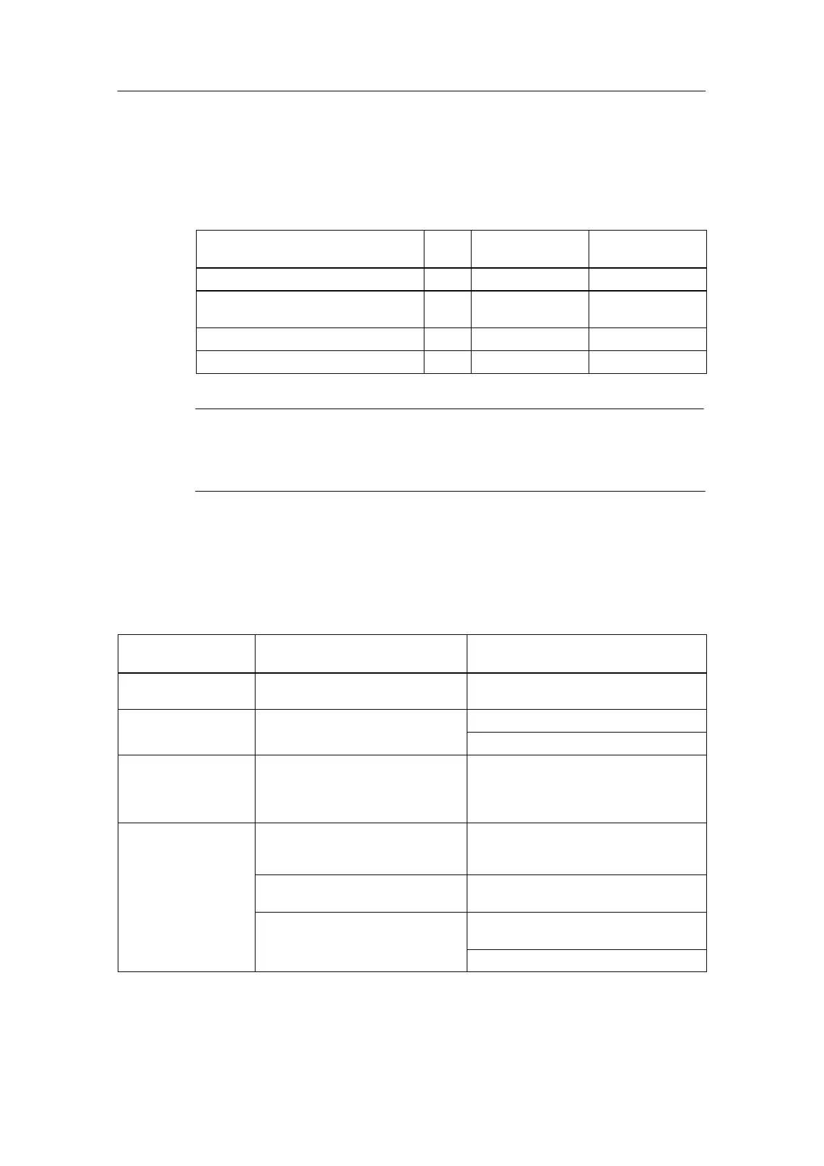
The table below gives an overview of the diagnostic messages for the analog
output modules.
Table 4-47 Diagnostics Messages of the Analog Output Modules
Diagnostics Message
LED Diagnostics Ef-
fective for
Parameters can
be assigned
External auxiliary supply missing SF Module No
Configuring/parameter assignment
error
SF
Channel Yes
Short-circuit to M SF Channel Yes
Wire-break SF Channel Yes
Note
A prerequisite for detecting the errors indicated by programmable diagnostic
messages is that you have assigned parameters to the analog module accordingly
in STEP 7.
Causes of errors and remedial measures for analog input modules
Table 4-48 Diagnostics Messages of the Analog Input Modules, Causes of Errors and
Remedial Measures
Diagnostics
Message
Possible Error Cause Remedy
External load voltage
missing
Load voltage L+ of module missing Feed supply L+
Configuring/paramete
Illegal parameters transferred to
Check measuring range module
assignment error module
Reassign module parameter
Common-mode error Potential difference U
CM
between
the inputs (M–) and reference
potential of measuring circuit (M
ANA
)
too high
Connect M– with M
ANA
Wire-break Resistance too high in the sensor
connection
Use different type of sensor or
connection, e.g. use conductors with a
larger cross-sectional core area
Open circuit between module and
sensor
Close circuit
Channel not connected (open) Disable channel group (“measuring
procedure” parameter
Connect channel
 Loading...


