RS 485 Repeater
7-7
Programmable Logic Controllers S7-300 Module Data
A5E00105505-03
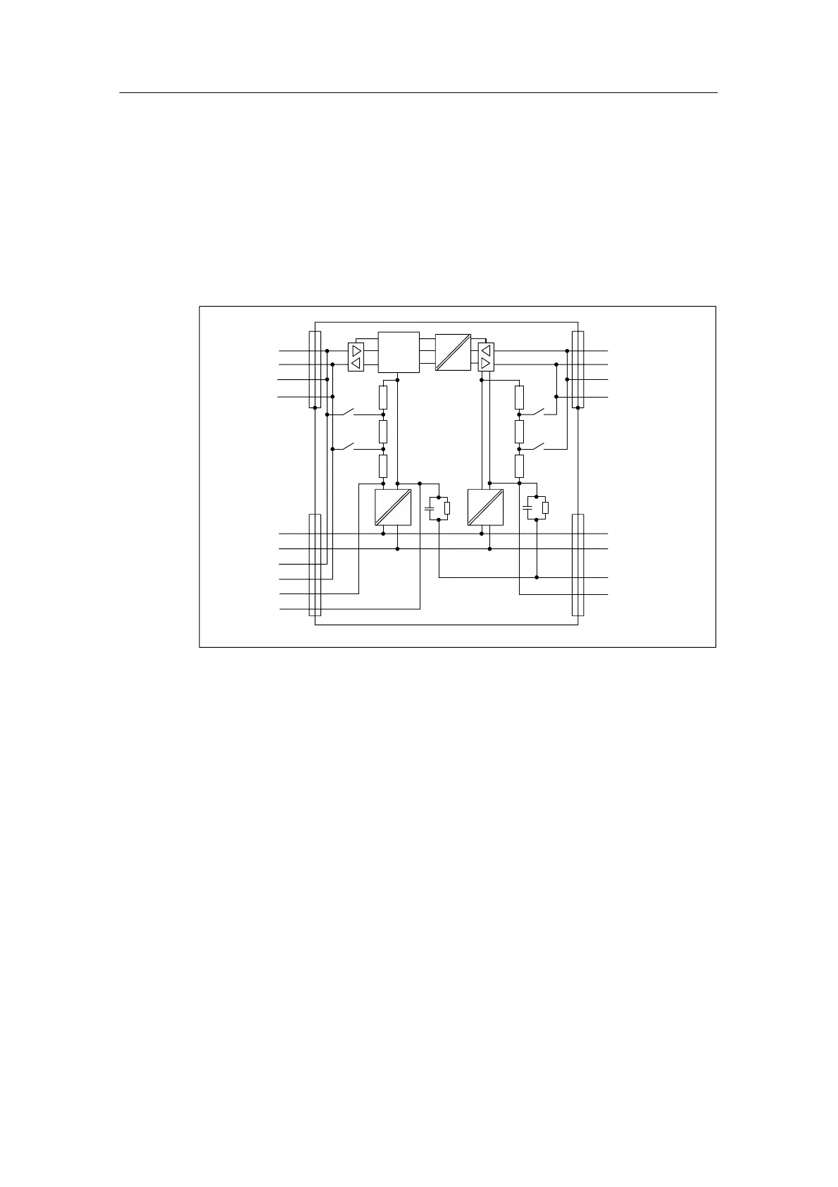
Block diagram of the RS 485 repeater
• Bus segment 1 and bus segment 2 are galvanically isolated from each other.
• Bus segment 2 and the PG/OP socket are galvanically isolated from each
other.
• Signals are amplified
– between bus segment 1 and bus segment 2
– between PG/OP socket and bus segment 2
5V
24V
Segment 2
A2
B2
A2
B2
Segment 1
A1
B1
A1
B1
PG/OP-
socket
L+ (24 V)
M
A1
B1
5 V
M5 V
L+ (24 V)
M
PE
M 5.2
Logic
5V
24V
1M1M
Figure 7-3 Block diagram of the RS 485 repeater

 Loading...


