Analog Modules
4-158
Programmable Logic Controllers S7-300 Module Data
A5E00105505-03
To use the following preset measuring methods and measuring ranges, you only
have to change the measuring range module to the corresponding setting.
Parameter assignment in STEP 7 is not necessary.
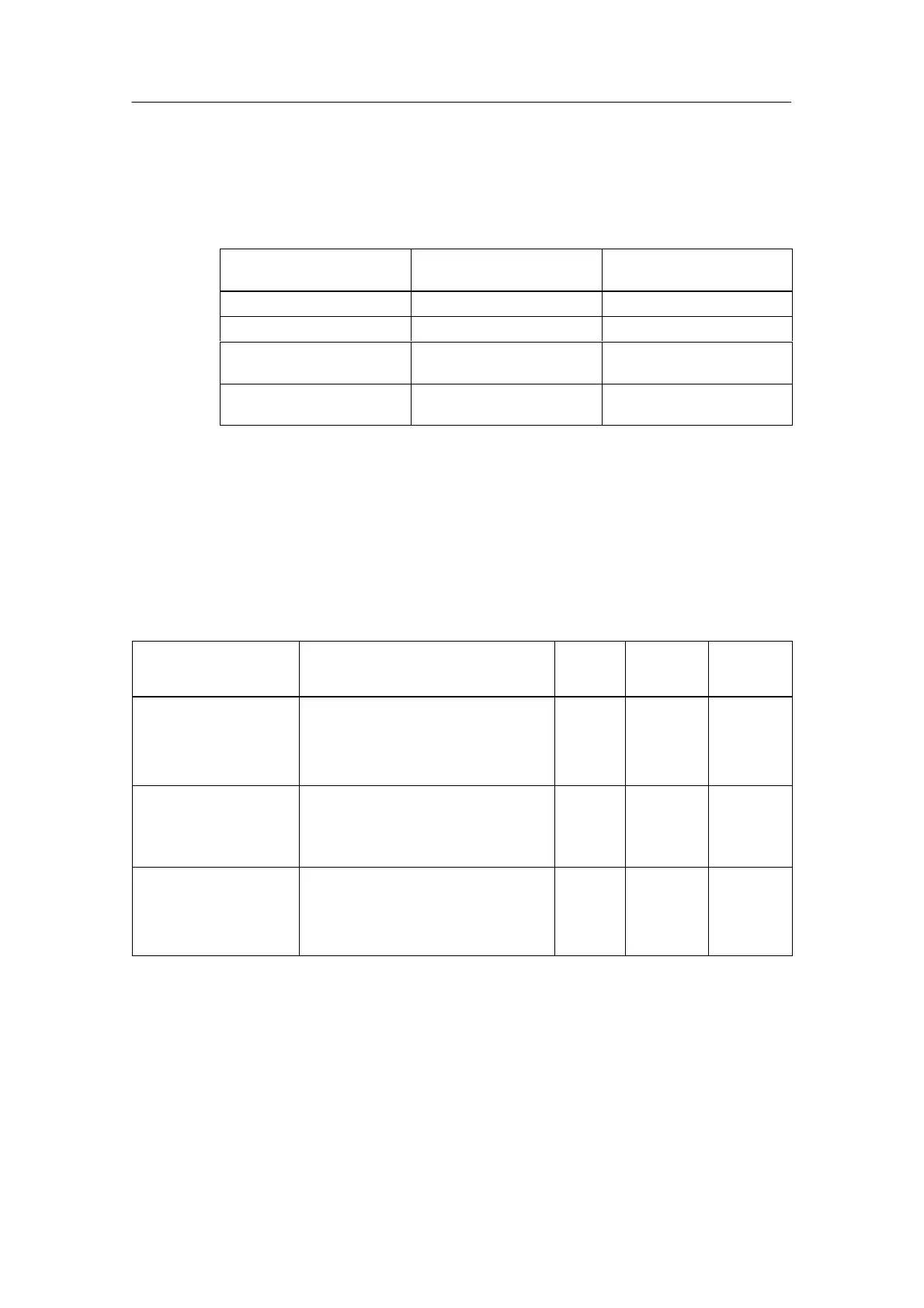
Table 4-80 Default Settings of the SM 331; AI 2 x 12 bits Using Measuring Range Module
Measuring Range
Module Setting
Measuring Method Measuring Range
A Voltage "1000 mV
B Voltage "10 V
C Current,
Four-wire transmitter
4 to 20 mA
D Current,
Two-wire transmitter
4 to 20 mA
Parameter
You will find a description of the general procedure for assigning parameters to
analog modules in Section 4.7.
An overview of the parameters that you can set and their default settings are
shown in the table below.
Table 4-81 Parameters of the SM 331; AI 2 x 12 bits
Parameter
Value Range Default
Settings
Para-
meter
Type
Scope
Enable
• Diagnostic interrupt
• Hardware interrupt
upon limit violation
Yes/no
Yes/no
No
No
Dynamic Module
Trigger for hardware
interrupt
• Upper limit value
• Lower limit value
32511 to –32512
–32512 to 32511
– Dynamic Channel
Diagnostics
• Group diagnostics
• With wire-break
check
Yes/no
Yes/no
No
No
Static
Channel
group
 Loading...


