Home
Siemens
Controller
6ES7 305-1BA80-0AA0
Siemens 6ES7 305-1BA80-0AA0 Reference Manual
4
of 1
of 1 rating
574 pages
Give review
Manual
Specs
To Next Page
To Next Page
To Previous Page
To Previous Page
Loading...
C-16
Programmable
Logic Controllers S7-300 Module Data
A5E00105505-03
C.5
Dimension
Drawings for Accessories
Shield
connecting element
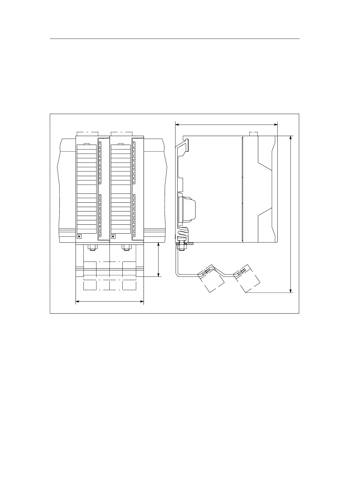
Figure C-21 shows the dimension drawing of the shield connecting element in
connection with two signal modules.
190
80
40
120
Figure C-21
2 Signal Modules with Shield Connecting Element
535
537
Table of Contents
Default Chapter
3
Controllers S7
3
Table of Contents
11
Start Information of ob 40: Which Event Has Triggered
20
1 General Technical Specifications
29
SIPLUS S7-300 Modules
29
Standards and Approvals
30
Use in an Industrial Environment
33
Electromagnetic Compatibility
34
Pulse-Shaped Interference
34
Sinusoidal Interference
35
Shipping and Storage Conditions for Modules and Backup Batteries
36
Shipping and Storage Conditions for Modules
36
Mechanical Conditions
36
Mechanical and Climatic Environmental Conditions for Operating S7-300S
37
Ambient Mechanical Conditions Test
38
Information on Insulation Tests, Protection Class and Degree of Protection
40
Test Voltages
40
Rated Voltages of the S7-300
41
Rated Voltages
41
SIPLUS S7-300 Modules
42
Mechanical and Climatic Ambient Conditions for the Operation of SIPLUS S7-300 Modules
44
SIPLUS S7-300 Modules Ambient Mechanical Conditions Test
44
Climatic Conditions
45
SIPLUS S7-300 Modules Climatic Conditions
45
Use of the et 200M / S7-300 in a Zone 2 Potentially Explosive Area
45
2 Power Supply Modules
69
Power Supply Module PS 305; 2 A; (6ES7305-1BA80-0AA0)
70
Wiring Schematic of the PS 305 Power Supply Module (2 A)
71
Basic Circuit Diagram of the PS 305 Power Supply Module (2 A)
73
Reaction of the PS 305 Power Supply Module (2 A) to Atypical Operating Conditions
73
Power Supply Module PS 307; 2 A; (6ES7307-1BA00-0AA0)
74
Wiring Schematic of the PS 307 Power Supply Module (2 A)
74
Basic Circuit Diagram of the PS 307 Power Supply Module (2 A)
75
Reaction of the PS 307 Power Supply Module (2 A) to Atypical Operating Conditions
75
Reaction of the PS 307 Power Supply Module (5 A) to Atypical Operating Conditions
75
Power Supply Module PS 307; 5 A; (6ES7307-1Eax0-0AA0)
77
Wiring Schematic of the PS 307 Power Supply Module (5 A)
78
Basic Circuit Diagram of the PS 307 Power Supply Module (5 A)
78
Reaction of the PS 307 Power Supply Module (5 a to Atypical Operating Conditions
79
Power Supply Module PS 307; 10 A; (6ES7307-1KA00-0AA0)
82
Wiring Schematic of the PS 307 Power Supply Module (10 A)
82
Basic Circuit Diagram of the PS 307 Power Supply Module (10 A)
83
Reaction of the PS 307 Power Supply Module (10 A) to Atypical Operating Conditions
83
3 Digital Modules
85
Module Overview
88
Digital Input Modules: Characteristics at a Glance
88
Digital Input Modules: Characteristics at a Glance (Continued)
89
Digital Output Modules: Characteristics at a Glance
90
Digital Output Modules: Characteristics at a Glance (Continued)
91
Relay Output Modules: Characteristics at a Glance
92
Digital Input/Output Modules: Characteristics at a Glance
93
Sequence of Steps from Choosing to Commissioning the Digital Module
94
Digital Module Parameter Assignment
95
Diagnostics of the Digital Modules
96
Digital Input Module SM 321; DI 32 X VDC 24; (6ES7321-1BL00-0AA0)
97
Module View and Block Diagram of the Digital Input Module SM 321; DI 32 X 24 VDC
98
Terminal Assignment of the SM 321; DI 32 X 24 VDC
98
Digital Input Module SM 321; DI 32 X 120 VAC; (6ES7321-1EL00-0AA0)
100
Moduleview and Block Diagram of Digital Input Module SM 321; DI 32 X 20 VAC
100
Digital Input Module SM 321; DI 16 X VDC 24; (6ES7321-1BH02-0AA0)
102
Module View and Block Diagram of Digital Input Module SM 321; DI 16 X 24VDC
102
Digital Input Module SM
104
DI 16 X 24 VDC High Speed; (6ES7321-1BH10-0AA0)
104
DI 16 X 24VDC High Speed
104
Digital Input Module SM 321; DI 16 X DC
106
With Hardware and Diagnostic Interrupts, Clocked; (6ES7321-7BH01-0AB0)
106
Module View and Block Diagram of Digital Input Module SM 321; DI 16 X 24 VDC
107
Terminal Assignment for Redundant Supply of Encoders of SM 321; DI 16 X VDC
108
Terminal Assignment for Resistive Circuit of the Encoder of the SM 321; DI 16 X 24 VDC
108
Synchronicity
110
Assigning Parameters to SM 321; DI 16 X VDC 24
111
Parameters of the SM 321; DI 16 X VDC 24
111
Assigning Interrupt Parameters to the Inputs of the SM 321; DI 16 X VDC
112
Tolerances of the Input Delays of SM 321; DI 16 X VDC
112
Behavior and Diagnostics of the SM 321; DI 16 X 24 VDC
113
Dependencies of Input Values on the Operating Mode of the CPU and Supply Voltage L+ of the SM 321; DI 16 X VDC
113
Diagnostic Messages of the SM 321; DI 16 X VDC
113
Diagnostic Messages of the SM 321; DI 16 X DC 24 V, Causes of Error and Remedial Action
115
Interrupts of the SM 321; DI 16 X 24 VDC
116
Digital Input Module SM 321; DI 16 X DC 24 V; Source Input; (6ES7321-1BH50-0AA0)
118
Module View and Block Diagram of Digital Input Module SM 321; DI 16 X 24 VDC (Source Input)
118
Digital Input Module SM 321; DI 16 X UC 24/48 V (6ES7321-1CH00-0AA0)
120
Module View and Block Diagram of Digital Input Module SM 321; DI 16 X 24/48VUC
120
Digital Input Module SM 321; DI 16 X VDC
122
(6Es7321-1Ch20-0Aa0)
122
Module View and Block Diagram of SM 321; DI 16 X 48-125 VDC
122
Digital Input Module SM 321; DI 16 X AC 120/230 V (6ES7321-1FH00-0AA0)
124
Module View and Block Diagram of the SM 321; DI 16 X 120/230VAC
124
Digital Input Module SM 321; DI 8 X VAC
126
(6Es7321-1Ff01-0Aa0)
126
Module View and Block Diagram of the SM 321; DI 8 X 120/230 VAC
126
Digital Input Module SM
128
DI 8 X 120/230 VAC ISOL (6ES7321-1FF10-0AA0)
128
Module View and Block Diagram of the SM 321; DI 8 X 120/230 VAC ISOL
128
Digital Output Module SM 322; DO 32 X 24 VDC/ 0.5 A; (6ES7322-1BL00-0AA0)
130
Module View and Block Diagram of Digital Output Module SM
131
Terminal Assignment of the SM 322; DO 32 X 24 VDC
131
Terminal Assignment of the SM 322; DO 32 X 24 VDC
132
Digital Output Module SM 322; DO 32 X VAC 120/230/1 A; (6ES7322-1FL00-0AA0)
133
Terminal Assignment and Block Diagram of the SM 322; D0 32 X VAC 120/230 /1 a
134
Terminal Assignment of the SM 322; DO 32 X AC 120/230 V/1 a
135
Digital Output Module SM 322; DO 16 X DC 24 V/ 0.5 A; (6ES7322-1BH01-0AA0)
137
Module View and Block Diagram of the SM 322; DO 16 X 24 VDC/0.5 a
138
Digital Output Module SM 322; DO 16 X 24 VDC/0.5 a High Speed
140
(6Es7322-1Bh10-0Aa0)
140
Module View and Block Diagram of the SM 322; DO 16 X 24 VDC/0.5 a High Speed
141
Digital Output Module SM 322; DO 16 X 24/48 VUC
143
(6Es7322-5Gh00-0Ab0)
143
Module View and Block Diagram of SM 322; DO 16 X 24/48 VUC
144
Parameters of Digital Output Module SM 322 DO 16 X UC24/48 V
147
Data Record No. 0 (Static Parameters)
147
Data Record No. 1 (Dynamic Parameters)
147
Structure of the Data Record for SM 322 DO 16 X
148
System Diagnostics for SM 322 DO 16 X
148
Digital Output Module SM 322; DO 16 X VAC 120/230/1 A; (6ES7322-1FH00-0AA0)
150
Module View and Block Diagram of the SM 322; DO 16 X 120/230 VAC/1 a
151
Digital Output Module SM 322; DO 8 X 24 VDC/2 a
153
(6Es7322-1Bf01-0Aa0)
153
Module View and Block Diagram of Digital Output Module SM
154
Digital Output Module SM 322; DO 8 X DC 24 V/ 0.5 a
156
With Diagnostic Interrupt; (6ES7322-8BF00-0AB0)
156
Module View of the SM 322; DO 8 X 24 V DC/0.5 a
157
Block Diagram of the SM 322; DO 8 X DC 24 V/0.5 a
158
Assigning Parameters to the SM 322; DO 8 X 24 VDC/0.5 a
160
Parameters of the SM 322; DO 8 X 24 VDC/0.5 a
160
Behavior and Diagnostics of the SM 322; DO 8 X 24 VDC/0.5 a
161
Dependence of the Output Values on the Operating Mode of the CPU and on the Supply Voltage L+ of the SM 322; DO 8 X 24 VDC/0.5 a
161
Diagnostic Messages of the SM 322; DO 8 X 24 VDC/0.5 a
162
Diagnostic Messages of the SM 322; DO 8 X 24 VDC/0.5 A, Causes of Error and Remedial Action
163
Interrupts of the SM 322; DO 8 X VDC 24/0.5 a
164
Digital Output Module SM 322; DO 8 X VDC 48-125/1,5 a
165
(6Es7322-1Cf00-0Aa0)
165
Digital Output Module SM 322; DO 8 X VAC 120/230/2 A; (6ES7322-1FF01-0AA0)
168
Module View and Block Diagram of the SM
169
Digital Output Module SM 322; DO 8 X 120/230 VAC/2 a ISOL (6ES7322-5FF00-0AB0)
171
Module View and Block Diagram of the SM 322; DO 8 X 120/230 VAC/2 a
172
Parameters of the SM 322; DO 8 X 120/230 VAC/2 a ISOL
174
Diagnostic Messages of the SM 322; DO 8 X 120/230 VAC/2 a ISOL
175
Error Causes and Remedies
175
Relay Output Module SM
177
DO 16 X Rel. 120/230 VAC; (6ES7322-1HH01-0AA0)
177
DO 16 X Rel. 120/230 VAC
178
Relay Output Module SM 322; DO 8 X Rel. 230 VAC; (6ES7322-1HF01-0AA0)
180
DO 8 X Rel. 230 VAC/5A; (6ES7322-5HF00-0AB0)
184
Relay Output Module SM 322 DO 8 X Rel. 230 VAC/5A; (6ES7322-5HF00-0AB0)
184
Special Characteristic for Operation with a Safe Electrical Extra-Low Voltage
186
SM 322; DO 8 X Rel. 230 VAC/5A Parameterization
188
Behavior and Diagnostics of the SM 322; DO 8 X 230 VDC/0.5 VAC/5A
188
Parameters of the SM 322; DO 8 X Rel. 230 VAC/5A
188
Diagnostic Messages of the SM 322; DO 8 X Rel. AC 230 VDC/0.5 a
188
Interrupts of the SM 322; DO 8 X Rel. 230 VAC/5A
189
Diagnostic Messages of the SM 322; DO 8 X Rel. 230 VAC/5A
189
Error Causes and Remedies
189
Relay Output Module SM 322; DO 8 X Rel. VAC 230/5 A; (6ES7322-1HF10-0AA0)
190
Special Characteristic for Operation with a Safe Electrical Extra-Low Voltage
191
Digital Input/Output Module SM 323; DI 16/DO 16 X 24 VDC/0.5 A; (6ES7323-1BL00-0AA0)
194
Terminal Assignment of the SM 323; DI 16/DO 16 X 24 VDC/0.5 a
195
Digital Input/Output Module SM 323; DI 8/DO 8 X VDC 24/0.5 A; (6ES7323-1BH01-0AA0)
197
Digital Input/Output Module SM
200
DI 8/DX 8 X DC 24 V/0.5 A; Parameterizable (6ES7327-1BH00-0AB0)
200
Terminal Assignment and Block Diagram of the SM 327 DI 8/DX 8 X DC 24 V/0.5 A, Parameterizable
201
Assigning Parameters to the SM 327; DI 8/DX 8 X VDC 24/0.5 a
203
Parameters of the SM 327; DI 8/DX 8 VDC 24/0.5 a
204
Re-Readability of the Outputs of the SM 327; DI 8/DX 8 X DC 24 V/0.5 a
205
4 Analog Modules
207
Module Overview
207
Sequence of Steps from Choosing to Commissioning the Module
207
Sequence of Steps from Choosing to Commissioning the Analog Module
207
Analog Value Representation
208
Setting the Measuring Method and Measuring Ranges of Analog Input Channels
208
Analog Module Parameter Assignment
208
Connecting Voltage Sensors
208
Connecting Current Sensors
208
Connecting Thermocouples
208
Module Overview
209
Example: Bit Pattern of a 16-Bit and a 13-Bit Analog Value
216
Possible Analog Value Resolutions
217
Bipolar Input Ranges
218
Analog Value Representation in Voltage Measuring Ranges + 10 V to + 1 V
219
Analog Value Representation in Voltage Measuring Ranges + 500 MV to + 80 MV
219
Analog Value Representation in Voltage Measuring Ranges 1 to 5 V and 0 to 10 V
219
Analog Value Representation in Current Measuring Ranges + 20 Ma to + 3.2 Ma
220
Analog Value Representation in Current Measuring Ranges 0 to 20 Ma and 4 to 20 Ma
220
Analog Value Representation for Resistance Type Transmitters
221
And from 150 W to 600 W
221
Current Measuring Ranges 0 to 20 Ma and 4 to 20 Ma
221
Analog Value Representation for RTD Resistance Temperature Detectors PT 100, 200, 500, 1000
222
Analog Value Representation for RTD Resistance Temperature Detectors Ni100, 120, 200, 500, 1000, LG-Ni 1000
223
Analog Value Representation for RTD Resistance Temperature Detectors Cu 10
224
Analog Value Representation for Thermocouples Type B
225
Analog Value Representation for Thermocouples Type C
225
Analog Value Representation for Thermocouples Type E
226
Analog Value Representation for Thermocouples Type J
226
Analog Value Representation for Thermocouples Type K
227
Analog Value Representation for Thermocouples Type L
227
Analog Value Representation for Thermocouples Type N
228
Analog Value Representation for Thermocouples Type R, S
228
Analog Value Representation for Thermocouples Type T
229
Analog Value Representation for Thermocouples Type U
229
Bipolar Output Ranges
231
Analog Value Representation in Output Range +10
232
Analog Value Representation in Output Range +20 Ma
232
Analog Value Representation in Output Ranges 0 and 20 Ma
232
Easing Measuring Range Modules from the Analog Input Module
235
Inserting Measuring Range Modules into the Analog Input Module
236
Example of the Influence of Smoothing on the Step Response
243
Settling and Response Times of the Analog Output Channels
244
Parameters of the Analog Input Modules
246
Parameters of the Analog Output Modules
249
Parameters of the Analog Input/Output Modules
250
Connecting Isolated Sensors to an Isolated AI
253
Connecting Non-Isolated Sensors to an Isolated AI
254
Connecting Non-Isolated Sensors to a Non-Isolated AI
255
Connecting Voltage Sensors
256
Connecting Two-Wire Transmitters to an Isolated AI
258
Four-Conductor Connection of Resistance Thermometers to an Isolated AI
260
Two-Conductor Connection of Resistance Thermometers to an Isolated AI
261
Connecting Thermocouples
264
Options for Compensation of the Reference Junction Temperature
265
Connection of Thermocouples with Internal Compensation to an Isolated AI
267
Connection of Thermocouples with Compensation Box to an Isolated AI
268
M72166-Xxx00) to an Isolated AI
269
Thermometers to the SM 331; AI 8 X TC
271
Connecting Loads/Actuators to Voltage Outputs
273
Connecting Loads to a Voltage Output of an Isolated AO over a Four-Conductor Connection
274
Connecting Loads to a Voltage Output of a Non-Isolated AO over a Two-Conductor Connection
275
Connecting Loads/Actuators to Current Outputs
276
Diagnostics of the Analog Modules
277
Diagnostic Messages of the Analog Input Modules
278
Diagnostics Messages of the Analog Output Modules
279
Diagnostics Messages of the Analog Output Modules, Causes of Errors and Remedial Measures
280
Interrupts of the Analog Modules
281
Start Information of ob 40: Which Event Has Triggered the Hardware Interrupt at the Limit Value
282
Analog Input Module SM 331; AI 8 X 16 Bits; (6ES7331-7NF00-0AB0)
283
Commissioning the SM 331; AI 8 X 16 Bits
287
Assignment of Channels of the SM 331; AI 8 X 16 Bits to Channel Groups
288
Measuring Methods and Measuring Ranges of the SM
289
AI 8 X 16 Bits
289
Measuring Ranges of the SM 331; AI 8 X 16 Bits
289
Analog Input Module SM 331; AI 8 X 16 Bits (6ES7331-7NF10-0AB0)
292
Module View and Block Diagram of the SM
293
Commissioning the SM 331; AI 8 X 16 Bits
295
Parameters of the SM 331; AI 8 X 16 Bits
296
8-Channel Mode
298
4-Channel Mode
299
Measuring Methods and Measuring Ranges of the SM 331; AI 8 X16 Bits
300
Measuring Ranges of the SM 331; AI 8 X 16 Bits
301
Analog Input Module SM 331; AI 8 X 14 Bits High Speed; Synchronous
303
(6ES7331-7Hf0X-0AB0)
303
Synchronicity
306
Calculation of the Filter and Processing Time
308
Commissioning the SM 331; AI 8 X 14 Bits High Speed
309
Parameters of the SM 331; AI 8 X 14 Bits High Speed
310
AI 8 X 14 Bits High Speed
311
Measuring Ranges of the SM 331; AI 8 X 14 Bits High Speed
312
Analog Input Module SM 331; AI 8 X 13 Bits; (6ES7331-1KF01-0AB0)
314
Parameters of the SM 331; AI 8 X 13 Bits
319
Measuring Methods of the SM 331; AI 8 X 13 Bits
320
Analog Input Module SM 331; AI 8 X 12 Bits; (6ES7331-7KF02-0AB0)
321
Commissioning the SM 331; AI 8 X 12 Bits
325
Default Settings of the SM 331; AI 8 X 12 Bits Using Measuring Range Modules
326
Assignment of Channels of the SM 331; AI 8 X 12 Bits to Channel Groups
327
Measuring Methods and Measuring Ranges of the SM
328
AI 8 X 12 Bits
328
Measuring Ranges of the SM 331; AI 8 X 12 Bits
329
Analog Input Module SM 331; AI 8 X RTD (6ES7331-7PF00-0AB0)
331
Module View and Block Diagram of the SM 331; AI 8 X RTD
332
Commissioning the SM 331; AI 8 X RTD
335
Assignment of Channels of the SM 331; AI 8 X RTD to Channel Groups
337
Hardware Filter 8 Channels Scan Time
338
Software Filter 8 Channels Scan Time
339
Hardware Filter 4 Channels Scan Time
340
Measuring Methods and Measuring Ranges of the SM 331; AI 8 X RTD
341
Measuring Ranges of the SM331; AI 8 X RTD
342
Analog Input Module SM 331; AI 8 X TC (6ES7331-7PF10-0AB0)
344
Module View and Block Diagram of the SM 331; AI 8 X TC
345
Commissioning the SM 331; AI 8 X TC
349
Assignment of Channels of the SM 331; AI 8 X TC to Channel Groups
351
Hardware Filter 8 Channels Scan Time
352
Software Filter 8 Channels Scan Time
353
Hardware Filter 4 Channels Scan Time
354
Measuring Methods and Measuring Ranges of the SM 331; AI 8 X TC
356
Analog Input Module SM 331; AI 2 X 12 Bits; (6ES7331-7KB02-0AB0)
359
Commissioning the SM 331; AI 2 X 12 Bits
363
Default Settings of the SM 331; AI 2 X 12 Bits Using Measuring Range Module
364
Measuring Methods and Measuring Ranges of the SM
366
AI 2 X 12 Bits
366
Measuring Ranges of the SM 331; AI 2 X 12 Bits
367
Analog Output Module SM 332; AO 8 X 12 Bits; (6ES7332-5HF00-0AB0)
369
AO 8 X 12 Bits
370
Commissioning the SM 332; AO 8 X 12 Bits
372
Output Ranges of the Analog Output Module SM 332; AO 8 X 12 Bits
374
Analog Output Module SM 332; AO 4 X 16 Bit; Synchronous
375
6Es7332-7Nd01-0Ab0
375
Module View and Block Diagram of the SM 332; AO 4 X 16 Bits
376
Synchronicity
378
Calculation of the Processing Time and the Time for Updating the Output
379
Commissioning the SM 332; AO 4 X 16 Bit
380
Output Ranges of the Analog Output Module SM 332; AO 4 X 16 Bits
381
Analog Output Module SM 332; AO 4 X 12 Bits; (6ES7332-5HD01-0AB0)
382
AO 4 X 12 Bits
383
Commissioning the SM 332; AO 4 X 12 Bits
385
Output Ranges of the Analog Output Module SM 332; AO 4 X 12 Bits
387
Analog Output Module SM 332; AO 2 X 12 Bits; (6ES7332-5HB01-0AB0)
388
Commissioning the SM 332; AO 2 X 12 Bits
391
Output Ranges of the Analog Output Module SM
392
AO 2 X 12 Bits
392
Analog Input/Output Module SM334; AI 4/AO 2 X 8/8 Bits; (6ES7334-0CE01-0AA0)
394
AI 4/AO 2 X 8/8 Bits
395
Commissioning the SM 334; AI 4/AO 2 X 8/8 Bits
398
Analog Input/Output Module SM 334; AI 4/AO 2 X 12 Bits
400
6Es7334-0Ke00-0Ab0
400
Module View and Block Diagram of the SM 334; AI 4/AO 2 X 12 Bits
401
Measuring Ranges of the SM 334;AI 4/AO 2 X 12 Bits
405
Output Ranges of the SM 334;AI 4/AO 2 X 12 Bits
406
Special Signal Modules
407
Module Overview
408
Simulator Module SM 374; IN/OUT 16; (6ES7374-2XH01-0AA0)
409
Module View of the Simulator Module SM 374; IN/OUT 16
410
Dummy Module DM 370; (6ES7370-0AA01-0AA0)
411
Module View of the Dummy Module DM 370
412
Position Decoder Module SM 338; POS-INPUT; (6ES7338-4BC01-0AB0)
413
Synchronous Operation
414
Terminal Connection Diagram and Block Diagram
415
Encoder Value Acquisition
416
Functions of the SM 338; POS INPUT
416
Gray/Dual Converter
417
Transferred Encoder Value and Normalization
417
Freeze Function
418
SM 338; POS-INPUT Parameterization
419
Parameters of the SM 338; POS-INPUT
420
SM 338; POS-INPUT Addressing
421
Diagnosis of the SM 338; POS-INPUT
423
Diagnostic Messages of the SM 338; POS INPUT
424
Diagnostics Messages of the SM 338, Causes of Errors and Remedial Measures
425
Interrupts of the SM 338; POS INPUT
426
Technical Specifications of the 338; POS-INPUT
427
Interface Modules
429
Module Overview
430
Interface Module IM 360; (6ES7360-3AA01-0AA0)
431
Front View of the Interface Module IM 360
432
Interface Module IM 361; (6ES7361-3CA01-0AA0)
433
Front View of the Interface Module IM 361
434
Front View of the Interface Module IM 365
436
6 Interface Modules
431
RS 485 Repeater
437
Application and Characteristics; (6ES7972-0AA01-0XA0)
438
Appearance of the RS 485 Repeater; (6ES7972-0AA01-0XA0)
439
RS 485 Repeater in Ungrounded and Grounded Operation
440
7 RS 485 Repeater
438
Isolation between the Bus Segments
441
Technical Specifications
442
Block Diagram of the RS 485 Repeater
443
8 SIMATIC TOP Connect and SIMATIC TOP Connect TPA
445
Module Overview
446
Wiring Components
448
Threading the Round-Sheath Ribbon Cable into the Connector
449
Wiring the Front Connector Module
450
Wiring Rules for Connecting the Supply Voltage
451
Inserting the Connecting Cable into the Front Connector Module
452
Front Connector Module for 32-Channel Digital Modules
453
Connecting the Connecting Cable to the Terminal Block
454
Spring-Loaded Terminal Block
455
Wiring SIMATIC TOP Connect with Digital Modules
456
Wiring the Module with Terminal Block for One-Conductor Connection
458
Wiring a Digital Module with Terminal Block for a One-Conductor Connection
459
Wiring the Module with Terminal Block for Three-Conductor Connection
460
Wiring a Digital Module with Terminal Block for a Three-Conductor Connection
461
Wiring the Module with Terminal Block for 2A Modules
462
Wiring with Terminal Block for 2A Module
463
Wiring SIMATIC TOP Connect TPA with Analog Modules
464
SIMATIC TOP Connect TPA Terminal Assignment and Terminal Allocation
465
Terminal Assignment of Analog Module to SIMATIC TOP Connect TPA
466
Connecting the Signal-Line Shield
467
Connection Example
468
A.1 How to Assign the Parameters for Signal Modules in the User Program
469
A5E00105505
471
A.3 Parameters of the Digital Output Modules
473
A.4 Parameters of the Analog Input Modules
475
A.5 Parameters of the SM 331; AI 8 X RTD
479
A-13 Parameters of the SM 331; AI 8 X TC
487
A-14 Codes of Operating Modes of the SM 331; AI 8 X TC
492
A-16 Codes for the Measuring Ranges of the SM 331; AI 8 X TC
493
A-17 Codes of Reaction to Open Thermocouple of the SM 331; AI 8 X TC
494
A.7 Parameters of the SM 331; AI 8 X 13 Bits
495
A-19 Codes for Temperature Measurement of the Analog Input Module
496
A-22 Codes for Temperature Measurement of the Analog Input Module
497
A.8 Parameters of the SM 331; AI 8 X 16 Bits
498
A-26 Codes for the Measuring Ranges of the SM 331; AI 8 X16 Bits
503
A-28 Parameters of the Analog Output Modules
504
A-29 Codes for the Output Ranges of the Analog Output Modules
506
A-30 Parameters of the SM 332; AO 8 X 12 Bits
507
A-32 Parameters of the Analog Input/Output Modules
509
A-33 Codes for the Measuring Ranges of the Analog Input/Output Modules
511
B.1 Evaluating Diagnostic Data of the Signal Modules in the User Program
513
B.2 Structure and Content of Diagnostic Data Bytes 0 to 7
514
B.3 Channel-Specific Diagnostic Data from Byte 8
517
B.4 Diagnostic Data of the SM 338; POS-INPUT
519
Power Supply Modules
521
C.1 Dimension Drawings of the Rails
522
C-3 Dimension Drawing of the 830 MM Standard Rail
523
C-5 Dimension Drawing of the Rail with 160 MM Standard Width
524
C-7 Dimension Drawing of the Rail with 530 MM Standard Width
525
C-9 Dimension Drawing of the 2000 MM Rail
526
C-10 Complete Dimension Drawing of a Rail for "Insert and Remove" Function with Active Bus Module, S7-300 Module and Explosion-Proof Partition
527
C.2 Dimension Drawings of the Power Supply Modules
528
C-13 Power Supply Module PS 307; 5 a
529
C-14 Power Supply Module PS 307; 10 a
530
C-15 Dimension Drawing of the Power Supply Module PS 307; 5 a with Cpus 313/314/315/315-2 DP. Front View
531
C-16 Dimension Drawing of the Power Supply Module PS 307; 5 a with Cpus 313/314/315/315-2 DP. Side View
532
C.3 Dimension Drawings of the Interface Modules
533
C-19 Interface Module IM 365
534
C.4 Dimension Drawings of the Signal Modules
535
C.5 Dimension Drawings for Accessories
536
C-22 SIMATIC TOP Connect, 3-Tier
537
C-24 SIMATIC TOP Connect, 1-Tier
538
C-26 RS 485 Repeater on S7-300 Rail
539
E.1 What Is ESD?
544
E.2 Electrostatic Charging of Persons
545
E.3 General Protective Measures against Electrostatic Discharge Damage
546
Glossary
549
Index
559
Analog Modules
561
5 Special Signal Modules
563
RS 485 Repeater
565
SIMATIC TOP Connect TPA
566
Other manuals for Siemens 6ES7 305-1BA80-0AA0
Manual
594 pages
Hardware And Installation Manual
242 pages
Technical Data
244 pages
Technical Data Manual
252 pages
Product Information
208 pages
Quick Start
82 pages
Operating Instructions
5 pages
Function Manual
332 pages
Equipment Manual
79 pages
Installation And Hardware Manual
20 pages
Getting Started
100 pages
4
Based on 1 rating
Ask a question
Give review
Questions and Answers:
Need help?
Do you have a question about the Siemens 6ES7 305-1BA80-0AA0 and is the answer not in the manual?
Ask a question
Siemens 6ES7 305-1BA80-0AA0 Specifications
General
Brand
Siemens
Model
6ES7 305-1BA80-0AA0
Category
Controller
Language
English
Related product manuals
Siemens 6ES7 331-7SF00-0AB0
112 pages
Siemens 6ED1 052-1HB00-0BA2
236 pages
Siemens 6ED1 052-2MD00-0BA2
236 pages
Siemens 6ED1 052-1MD00-0BA2
236 pages
Siemens 6ED1 052-1CC00-0BA2
236 pages
Siemens 6ED1 053-1FB00-0BA2
236 pages
Siemens 6ED1 053-1FH00-0BA2
236 pages
Siemens 6MD86
1256 pages
Siemens RWF55.6
93 pages
Siemens LFL1.635
25 pages
Siemens QAA78.610
221 pages
Siemens SIMODRIVE 611 universal
930 pages
 Loading...


