Special Signal modules
5-9
Programmable Logic Controllers S7-300 Module Data
A5E00105505-03
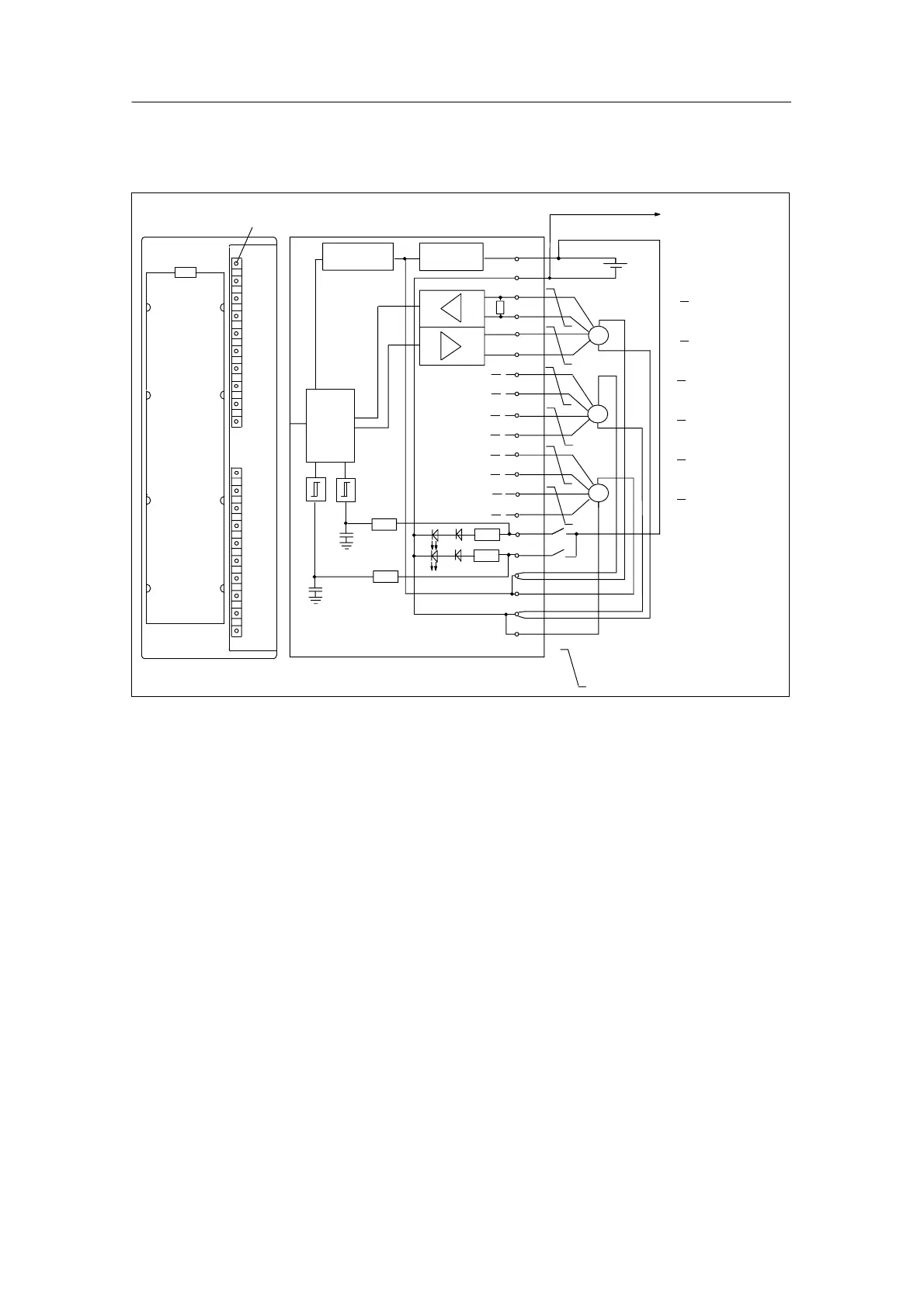
5.4.2 Terminal Connection Diagram and Block Diagram
Fault indicator – red
1
2
3
4
5
6
7
8
9
10
11
12
13
14
15
16
17
18
19
20
L+
24V
OD (Data)
OD (Data)
OC (Clock)
OC (Clock)
1D (Data)
1D (Data)
1C (Clock)
1C (Clock)
2D (Data)
2D (Data)
2C (Clock)
2C (Clock)
DI 0 (Digital-
DI 1 input)
DC24V (encoder)
DC24V (encoder)
M (encoder)
M (encoder)
SSI
SSI
SSI
Short-circuit
protection
Voltage monito-
ring
SF
S7–300 Backplane bus
Logic
M
RS 422
Twisted pair cables
DI 0
DI 1
Connection to the
ground of the CPU
Figure 5-3 Module View and Block Diagram of the SM 338; POS-INPUT
Wiring rules
Please observe the following important rules of the wiring of the module:
• The ground of the encoder supply is connected non-isolated to the ground of
the CPU. Thus, connect pin 2 of the SM 338 (M) with low impedance with the
ground of the CPU.
• The encoder lines (pins 3 to 14) must be twisted pairs and shielded. Apply the
shield to both sides.
For the shield connection to the SM 338, use the shield connection element
(order number 6ES7390-5AA00-0AA0).
• If the output current (900 mA) of the encoder supply is exceeded, then you
must connect an external power supply.

 Loading...


