Parameter Sets for Signal Modules
A-9
Programmable Logic Controllers S7-300 Module Data
A5E00105505-03
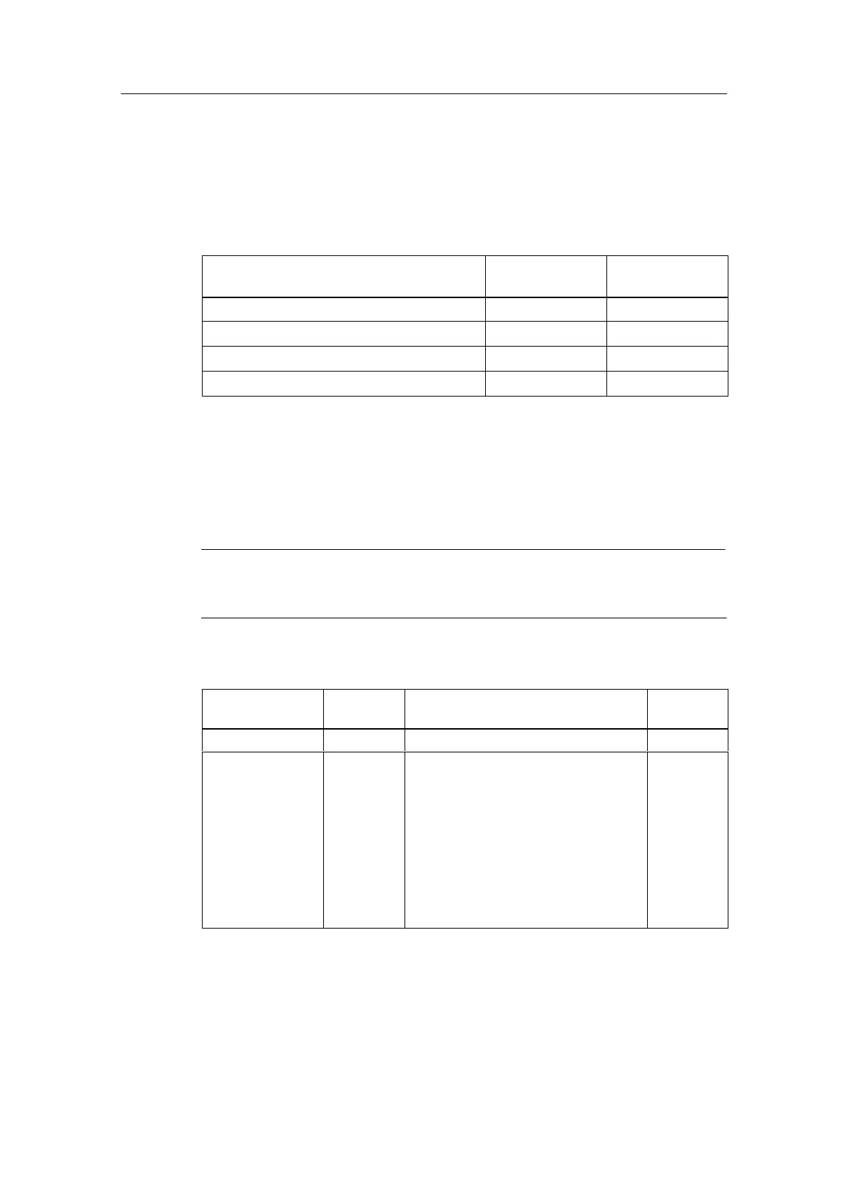
Interference frequency suppression
The table below contains the codes for the different frequencies, which you enter in
byte 1 of data record 1 (refer to Figure A-3). You must count the resulting
integration time separately for each channel!
Table A-5 Codes for Interference Suppression of the Analog Input Modules
Interference Suppression Integration
Time
Code
400 Hz 2.5 ms 2#00
60 Hz 16.7 ms 2#01
50 Hz 20 ms 2#10
10 Hz 100 ms 2#11
Measuring methods and measuring ranges
The table below contains all the measuring methods and measuring ranges of the
analog input modules and their codes. You must enter these codes in bytes 2 to 5
of data record 1 (refer to Figure A-3).
Note
Please note that a measuring range module may need to be reconnected,
depending on the measuring range (see Chapter 4)!
Table A-6 Codes for the Measuring Ranges of the Analog Input Modules
Measuring
Method
Code Measuring Range Code
Deactivated 2#0000 Deactivated 2#0000
Voltage 2#0001 " 80 mV
" 250 mV
" 500 mV
" 1 V
" 2.5 V
" 5 V
1 to 5 V
0 to 10 V
" 10 V
" 25 mV
" 50 mV
2#0001
2#0010
2#0011
2#0100
2#0101
2#0110
2#0111
2#1000
2#1001
2#1010
2#1011
 Loading...


