3
Product Information on the Manual
A5E00201782-02
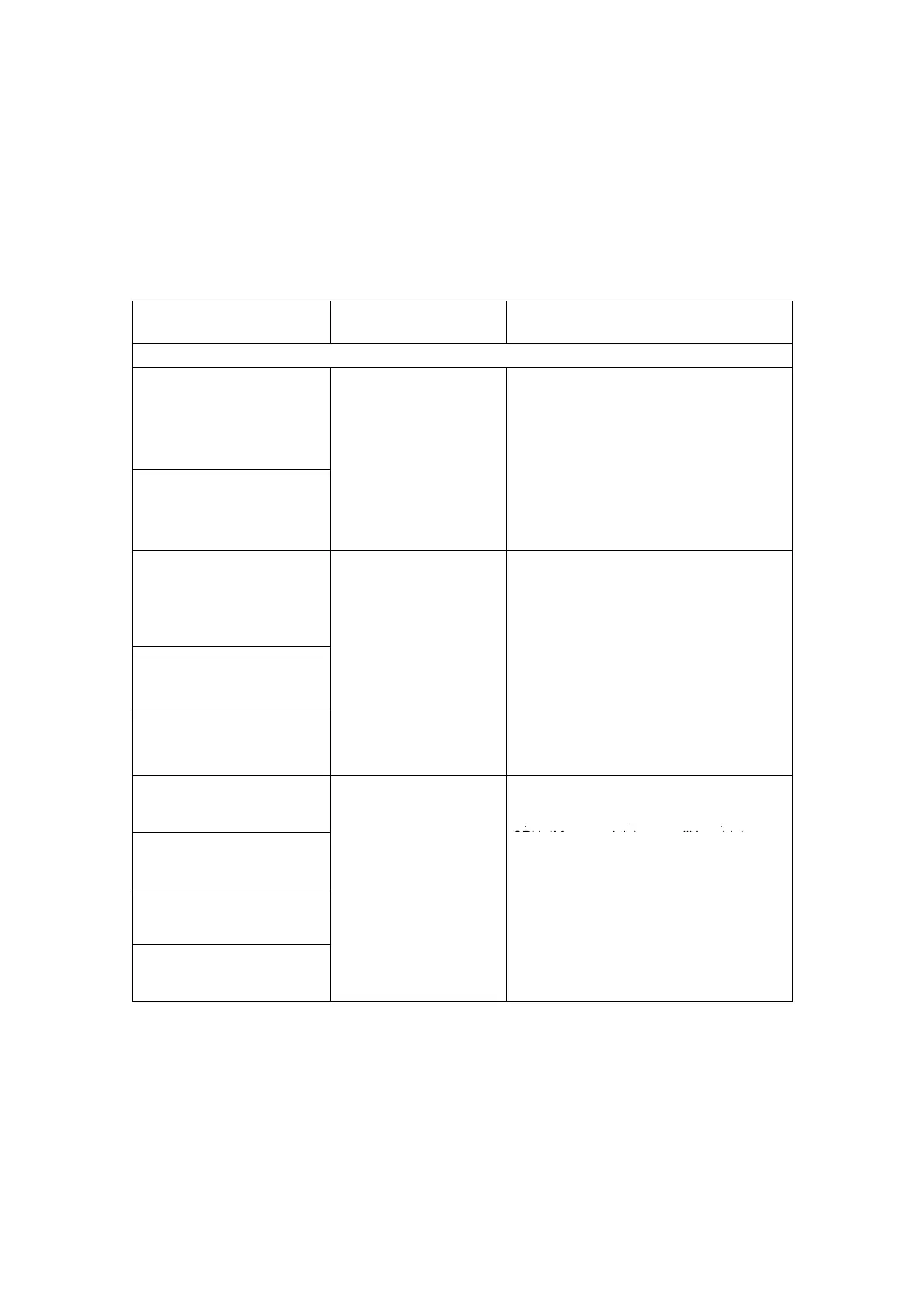
Notes on the table
There is a separate table for each manual that describes the technical
specifications of the signal modules of the S7-300 product family.
The “Behavior of the Inputs/Outputs” column indicates the behavior of the
inputs/outputs when reparameterization is carried out in RUN mode, provided they
are not affected by reparameterization.
Module
Behavior of the
inputs/outputs
Peculiarities when reparameterizing
S7-300 module specifications
6ES7 321-7BH00-0AB0
6ES7 321-7BH80-0AB0
SM 321; DI 16 DC 24 V;
with hardware interrupt and
diagnostic interrupt
Supply the last valid
process value before
parameterization
---
6ES7 321-7BH01-0AB0
SM 321; DI 16 DC 24 V;
with hardware interrupt and
diagnostic interrupt, clocked
6ES7 322-8BF00-0AB0
6ES7 322-8BF80-0AB0
SM 322; DO 8 DC 24 V/
0.5 A; with diagnostic
interrupt
Output the last valid
6ES7 322-5FF00-0AB0
SM 322;DO 8 AC 120/230V/
2A ISOL
parameterization
6ES7 322-5HF00-0AB0
SM 322;
DO 8 Rel. AC 230V/5A
6ES7 331-7NF00-0AB0
SM 331; AI 8 16 Bit
SF LED shines:
If there was a pending diagnosis before
reparameterization, the SF LEDs (on the
CPU, IM, or module) may still be shining
6ES7 331-7NF10-0AB0
SM 331; AI 8 16 Bit
Supply the last valid
process value before
reparameterization, the SF LEDs (on the
CPU, IM, or module) may still be shining
although there is no longer a pending
diagnosis and the module is working
6ES7 331-7PF00-0AB0
SM 331; AI 8 RTD
Remedy:
• Only reparameterize when there is no
pending diagnosis on the module, or
6ES7 331-7PF10-0AB0
SM 331; AI 8 TC
pending diagnosis on the module, or
• Remove the module, and then plug it in
again
 Loading...


