Siemens Energy & Automation 11-11
SIMOREG DC Master Base Drive Panel Operating Instructions
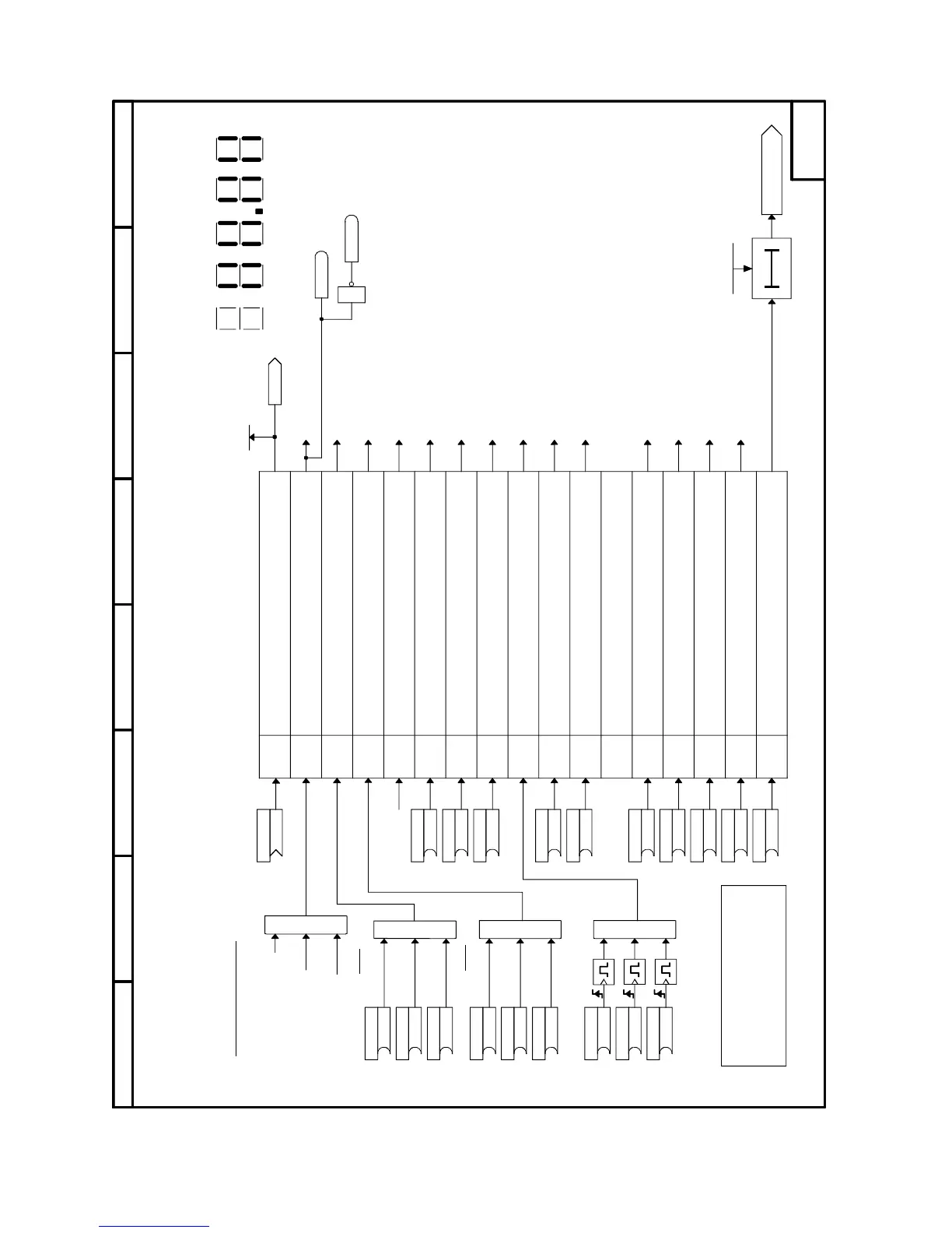
Sheet 10 Control Word 1
&
&
1
≥
321Bit0
4
5
6
7
Bit8
910
11
121314
15
1
≥
1
Bit 0
Bit 1
Bit 2
Bit 3
Bit 4
Bit 5
Bit 6
Bit 7
Bit 8
Bit 9
Bit 10
Bit 11
Bit 12
Bit 13
Bit 14
Bit 15
P667.B (0)
B
P666.B (0)
B
P665.B (0)
B
B
B
B
B
B
P655.B (1)
B
P656.B (1)
P657.B (1)
P658.B (1)
P659.B (1)
P660.B (1)
P675.B (1)
B
P674.B (0)
B
P673.B (0)
B
P672.B (1)
B
P671.B (1)
B
P668.B (0)
B
P669.B (0)
B
P662.B (1)
B
P663.B (1)
B
P664.B (1)
B
<1>
<1>
r650
K0030
P360.01 (0ms)
(0...10000ms)
P648.B (9)
K
B0160
B0161
0=OFF1, shutdown via ramp-function generator followed by
pulse disable
1=ON, operating condition (edge-controlled)
0=OFF2, pulse disable, motor coasts to standstill
1=operating condition
0=OFF3, fast stop
1=operating condition
1=Enable, enable pulses
0=Pulse disable
1=Enable ramp-function generator
0=Set ramp-function generator to 0
1=Ramp-function generator start
0=Ramp-function generator stop
1=Enable setpoint
0=Disable setpoint
0 =>1 edge Acknowledge
1=Inching 1
1=Inching 2
1=Control requested
0=No control requested
1=Enable positive direction of rotation
0=Positive direction of rotation disabled
1=Enable negative direction of rotation
0=Negative direction of rotation disabled
1=Increase motorized potentiometer
1=Decrease motorized potentiometer
0=External fault 1
1=No external fault
Bit No.
Meaning
Pulse generator
Note:
Bit 10 must be set in the first PZD word
of the telegram received via the serial
interfaces to ensure that the process data
will be accepted as valid (cf. USS,
Profibus, etc.).
Control word 1
Control word 1
to sequencing control
to sequencing control
to sequencing control
to sequencing control,
to brake control
to sequencing control,
to brake control
Display of control word 1 (r650)
on 7-segment display
External fault 1
1 = "Fault F021"
to "Ramp-function generator"
to "Ramp-function generator"
to "Ramp-function generator"
"Inching setpoint 1" [ 2.3 ]
"Inching setpoint 2" [ 2.3 ]
When P648 = 9, bit-serial input of control bits (P654 to P675 are effective)
When P648 <> 9, word-serial input of control bits (P654 to P675 are not effective)
Terminals 37 and 38 are always active. They are ANDed to get bit 0 or bit 3.
TERMINAL 37 ON / OFF
INCHING ON / OFF
CRAWL ON / OFF
ENABLE
COAST STOP
NORMAL START / STOP
FAST STOP
FAULT ACK
87564321
6RA70 DC MASTER
SIMPLIFIED BLOCK DIAGRAM
(ALL AVAILABLE FUNCTIONS ARE NOT SHOWN ON SIMPLIFIED BLOCK DIAGRAM)
10
[ 2.2 ]
[ 2.2 ]
[ 2.7 ]
[ 2.7 ]
[ 2.7 ]
[ 2.7 ]
[ 3.2 ]
OR'd WITH P435.01
OR'd WITH P435.02

 Loading...