Siemens Energy & Automation 11-15
SIMOREG DC Master Base Drive Panel Operating Instructions
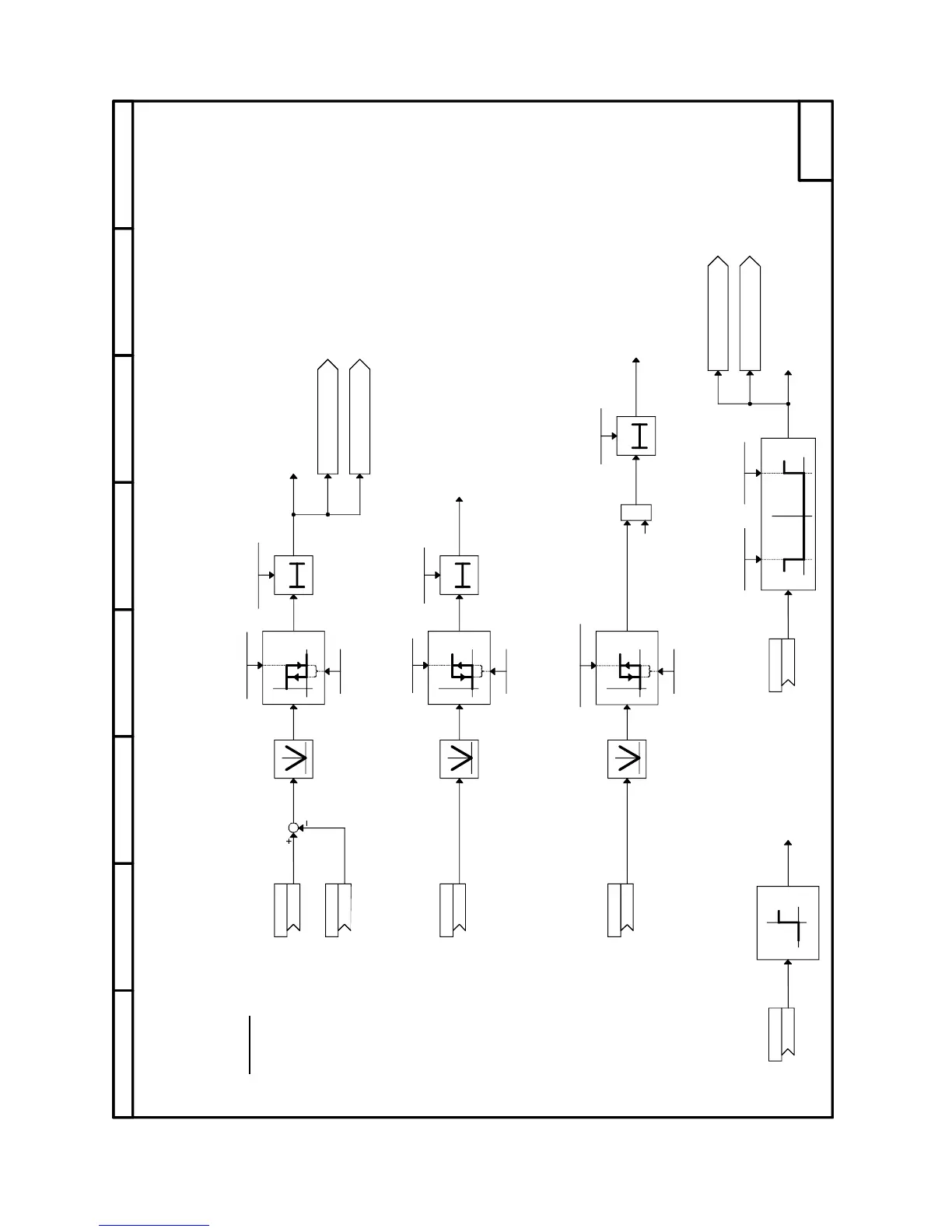
Sheet 14 Signals
87564321
6RA70 DC MASTER
SIMPLIFIED BLOCK DIAGRAM
(ALL AVAILABLE FUNCTIONS ARE NOT SHOWN ON SIMPLIFIED BLOCK DIAGRAM)
14
0T
0
1
T0
0
1
0
1
&
T
0
0
1
0
1
P381.F (-120.0)
(-199.9...0.0%)
P380.F (120.0)
(0.0...199.9%)
P388.F (3.00)
(0.00...199.99%)
P390.F (3.0)
(0.0...100.0 s)
P373.F (100.00)
(0.00...199.99%)
P374.F (3.00)
(0.00...199.99%)
P389.F (3.00)
(0.00...199.99%)
P370.F (0.50)
(0.00...199.99%)
P590 (170)
K
P591 (167)
K
P375.F (3.0)
(0.0...100.0 s)
P593 (167)
K
P088.F (3.0)
(0.0...100.0 s)
P594 (170)
K
P595 (167)
K
P371.F (0.50)
(0.00...199.99%)
P592 (167)
K
n(act)
n(max. neg. rot.) n(max. pos. rot.)
n(comp.)
OFF delay
n(comp.hyst.)
OFF shutdown speed
Firing pulse disable
OFF1 or OFF3 from
sequencing control
Comparison (time)
n(act)
OFF delay
Comparison (time)
n(set)
OFF shutdown speed (hyst.)
Setp./act.val. dev. (perm.)
Setp./act.val. dev. (time)
OFF delay
Setp./act.val. hyst.
Signals
n(act)
n(set)
n(act)
Comparison setpoint reached
to status word 1, bit 10
Positive speed setpoint
to status word 1, bit14
Overspeed to
status word 2, bit 18
Setpoint/act. value deviation
to status word 1, bit 8
1 = "Fault F031"
1 = "Fault F038"
1 = "Alarm A038"
1 = "Alarm A031"
[ 3.1 ]
[ 3.3 ]
[ 3.3 ]
[ 3.3 ]
[ 3.1 ]
[ 3.3 ]

 Loading...