Communication
2.2 PROFINET communication
SIMOCODE pro - Communication
Function Manual, 11/2018, A5E40508495002A/RS-AC/003
61
Configuring system redundancy with PROFINET IO
Requirements
In the example below, you will configure a redundant-system PROFINET configuration with
redundant I/Os as discussed in diagram "S7-400 H system with redundant I/Os" in the
previous chapter.
The PROFIBUS elements have been excluded from this example. Please refer to manual
Fault-tolerant S7-400H systems
(https://support.automation.siemens.com/WW/view/en/1186523) for basic instructions on
configuring H systems.
Set up a new H station in the SIMATIC Manager and open "HW Config" for the station.
1. Insert a rack 400 (e.g. UR2-H) for redundant controllers.
2. Insert a CPU 400-H PN/DP (e.g. CPU 4174-5H PN/DP).
3. Network the Ethernet interface in the normal way and set the IP parameters.
4. Configure a power supply module and the H-Sync modules.
5. Copy the station that you have set up: To do this, select the station and then select
command Edit → Copy followed by command Edit → Paste.
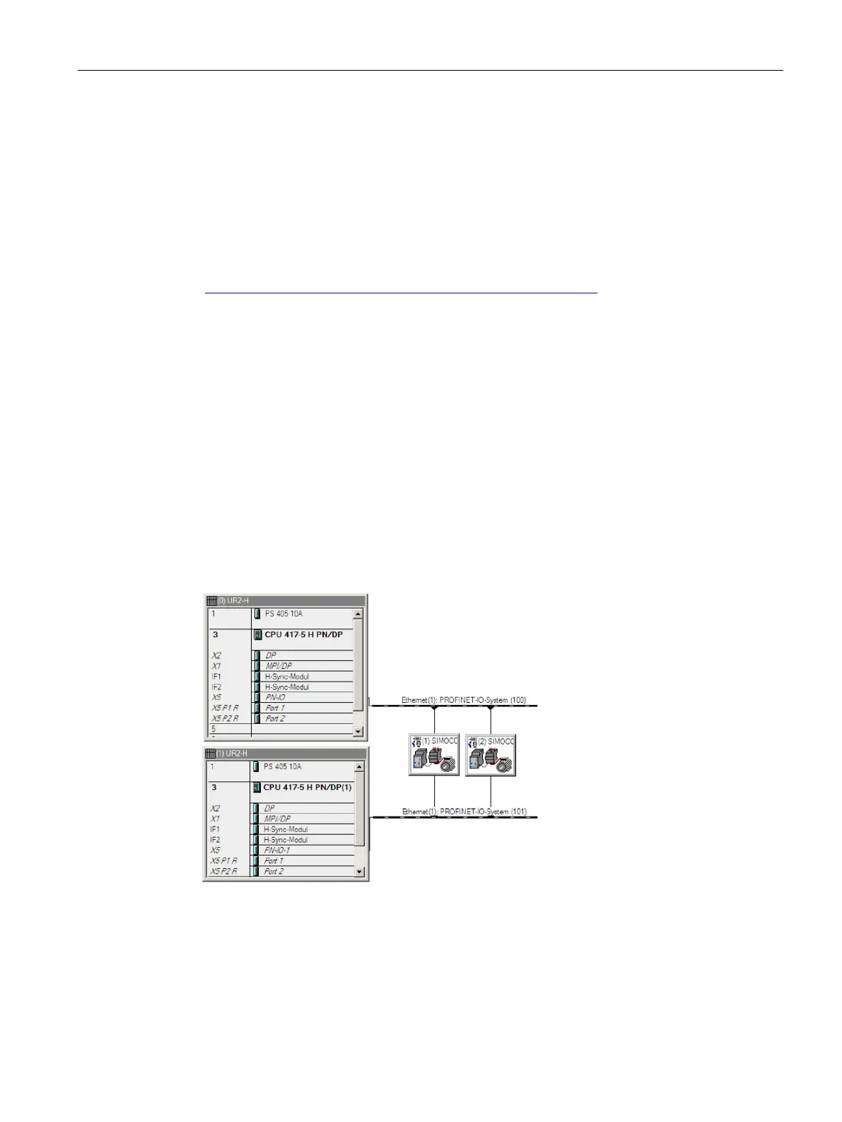
6. Configure SIMOCODE pro V PN (GP) as a redundant IO device by dragging the IO
devices in the normal way to one of the two IO systems. The modules will be connected
as redundant units (to both PROFINET lines) as standard.
Figure 2-19 SIMOCODE pro V PN (GP) as a redundant I/O unit in HW Config