Introduction
1.7 Coordinate systems
1-28
SINUMERIK 802D sl Operation and Programming Nibbling (BP-N), 06/2006 Edition
6FC5 398-3CP10-0BA0
1.7 Coordinate systems
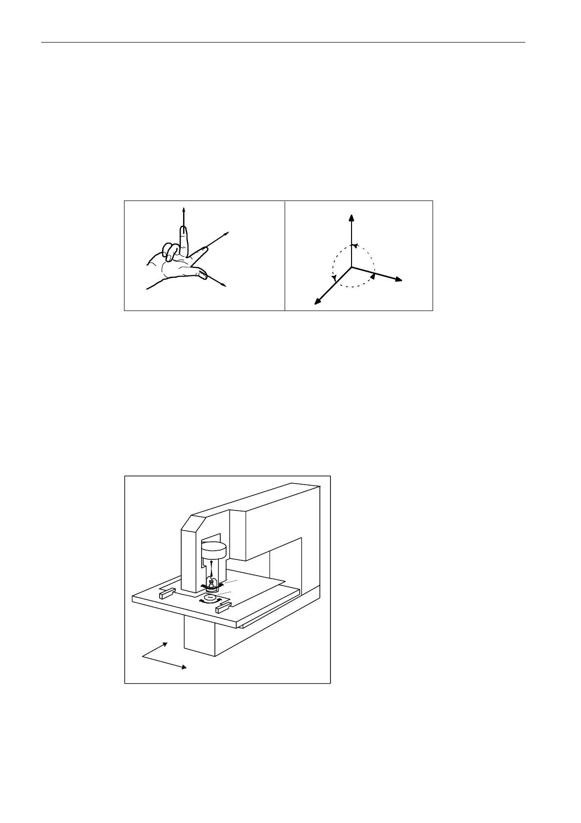
As a rule, a coordinate system is formed of three mutually perpendicular coordinate axes.
The positive directions of the coordinate axes are determined using the socalled “right-hand
three-finger rule”. The coordinate system is related to the workpiece and programming takes
place independently of whether the tool or the workpiece is being traversed. When program-
ming, it is always assumed that the tool traverses relative to the coordinate system of the
workpiece, which is intended to be stationary.
+ Z
+ Y
+ X
90°
+ Y
+ Z
+ X
90°
90°
Fig. 1-16 Definition of the directions of the axes one to another; right-angled
coordinate system
Machine coordinate system (MCS)
The orientation of the coordinate system relative to the machine depends on the machine
type. It can be rotated in different positions.
The axis directions follow the “Right-hand three-finger rule”. Seen from in front of the ma-
chine, the middle finger of the right hand points in the opposite direction to the infeed direc-
tion of the main spindle.
X
Y
C2
C
Fig. 1-17 Machine coordinates/machine axes

 Loading...


