Manually Controlled Mode
4.1 JOG mode – “Position” operating area
4-51
SINUMERIK 802D sl Operation and Programming Nibbling (BP-N), 06/2006 Edition
6FC5 398-3CP10-0BA0
Parameters
Table 4-1 Description of the parameters in the JOG start screen
Parameter Explanation
MCS
X
Y
C1
C2
Displays the address of the axes existing in the machine coordinate system (MCS)
+X
....
–Y
If you traverse an axis in the positive (+) or negative () direction, a plus or minus sign will appear in
the relevant field.
If the axis is already in the required position, no sign is displayed.
Position
mm
These fields display the current position of the axes in the MCS or WCS.
Repos. offset If the axes are traversed in the “Program interrupted” condition in the JOG mode, the distance tra-
versed by each axis is displayed referred to the interruption point.
G function Displays important G functions
Feed F mm/
min
Displays the path feedrate actual value and setpoint
Tool Displays the currently active tool with the current edge number
Softkeys
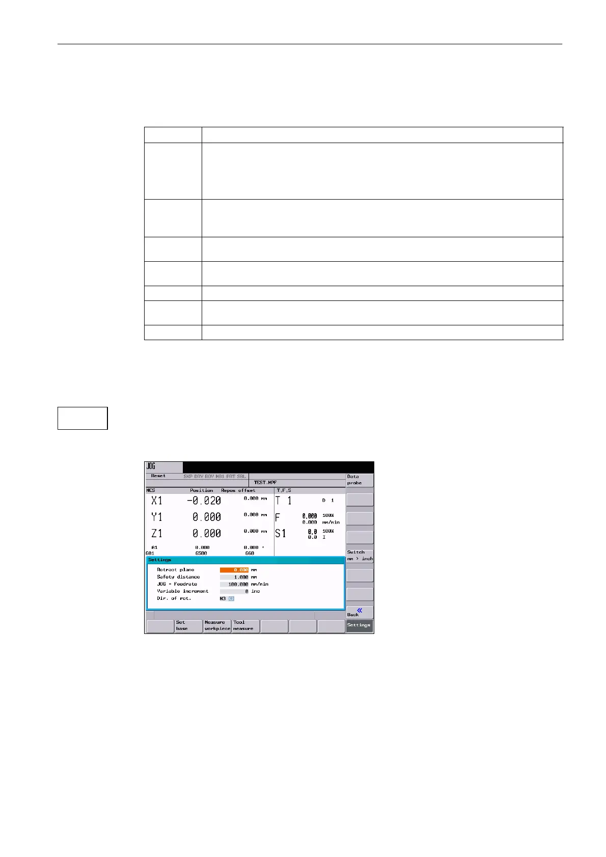
The interactive screenform shown below is intended to set the retraction plane, the safety
clearance and the direction of rotation of the spindle for automatically generated part pro-
grams in the MDA mode. Furthermore, the values for the JOG feedrate and the variable size
of increments can be set.
Fig. 4-3
Safety clearance: Safety clearance to the workpiece surface
This value defines the minimum clearance between the workpiece surface and the work-
piece.
JOG feedrate: Feedrate value in the JOG mode
Settings

 Loading...


