10.03
4.3 Closed-loop velocity control
4-111
Siemens AG, 2003. All rights reserved
SINUMERIK 840D/SIMODRIVE 611 digital, HLA Module (FBHLA) - 10.03 Edition
5414
SPEEDCTRL_REF_MODEL_FREQ [n] 0...7 index of the parameter set
Cross reference: -
Natural frequency of reference model Related to:
HLA
Protection level:
3/3
Unit:
Hz
Default:
150.0
Minimum:
0.0
Maximum:
1000.0
Data type:
FLOAT
Active:
Immediately
5415
SPEEDCTRL_REF_MODEL_DAMPING [n] 0...7 index of the parameter set
Cross reference: -
Reference model damping Related to:
HLA
Protection level:
3/3
Unit:
-
Default:
0.9
Minimum:
0.4
Maximum:
1.0
Data type:
FLOAT
Active:
Immediately
The dynamic response of the velocity control loop to control commands without
an I component in the velocity controller is simulated in the reference model. In
the ideal case of exact simulation, there is no deviation after the setpoint/actual
value comparison on the integrator under no-load conditions. In practice, veloc-
ity overshoots in the response to control commands can be reduced in this way.
The reference model is defined by setting the natural frequency (MD5414)
and damping (MD 5415) parameters.
Two control output filters have been implemented. As compared to the current
setpoint filter on electrical drives, the scope of functions has been extended by
the general band stop.
5200
NUM_OUTPUT_VCTRL_FILTERS [n] 0...7 index of the parameter set
Cross reference: -
Number of control output filters in velocity controller
Related to:
HLA
Protection level:
3/3
Unit:
-
Default:
0
Minimum:
0
Maximum:
2
Data type:
UNS.WORD
Active:
Immediately
The number of control output filters in the velocity controller is set in MD 5200.
No filters are active by default. Bandstop filters and 2nd-order low pass filters
can be selected and set in MD 5201: OUTPUT_FILTER_CONFIG.
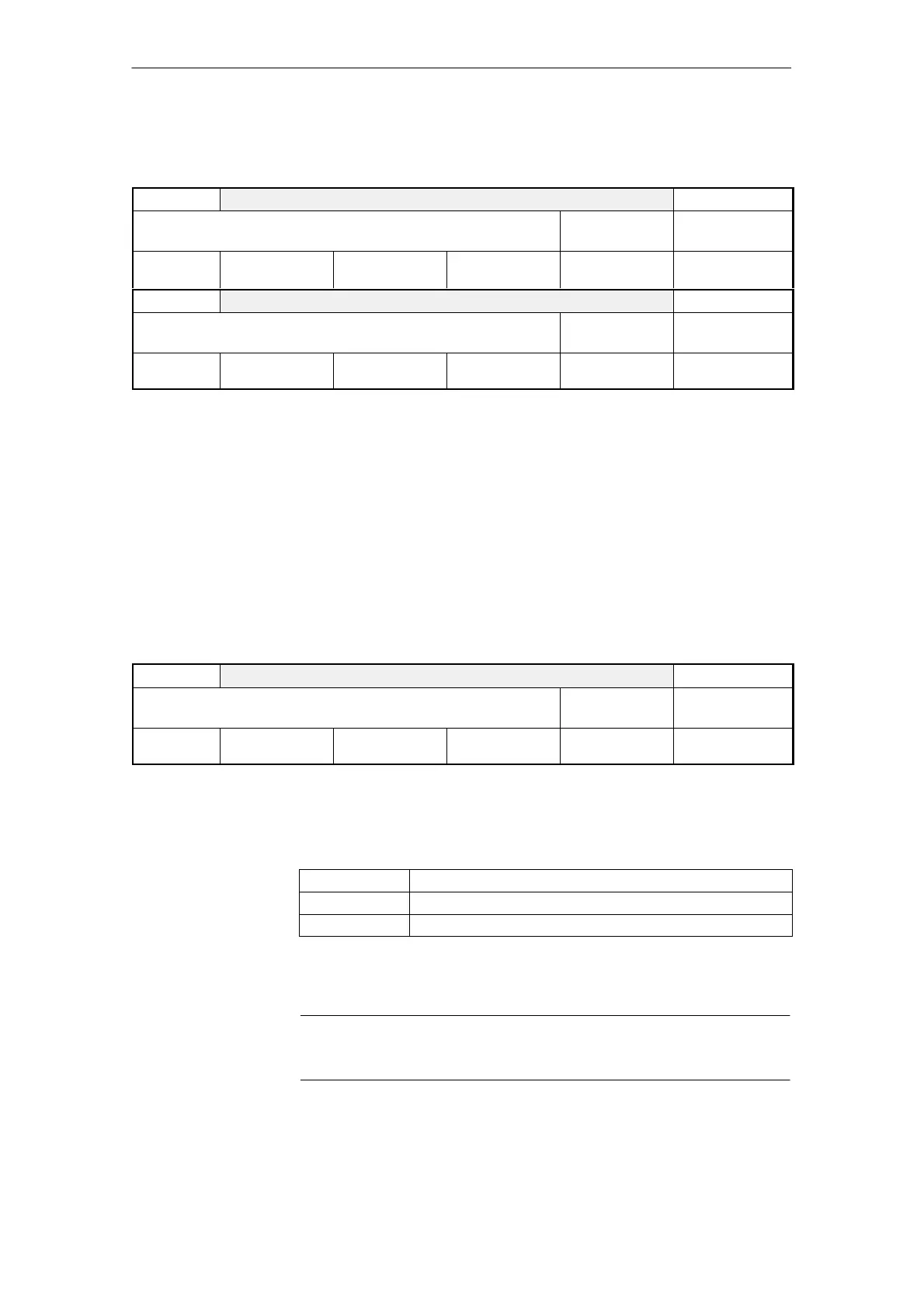
Table 4-1 Selection of number of control output filters in velocity controller
0 No control output filter active
1 Filter 1 active
2 Filters 1 and 2 active
Enter the configuration for 2 control output filters. Bandstops (BS) and low-pass
filters can be selected. The variable filter parameters are entered in the associ-
ated machine data.
Note
The filter machine data must be assigned before the filter type is configured.
Reference model
Control output,
velocity controller
4 Firmware Drive Functions
08.99
 Loading...


