10.03
4.9 Drive data
4-138
Siemens AG, 2003. All rights reserved
SINUMERIK 840D/SIMODRIVE 611 digital, HLA Module (FBHLA) - 10.03 Edition
Note
The mass of the drive is a critical parameter and should be calculated as
exactly as possible!
5151 CYLINDER_A_ORIENTATION Cross reference: -
Cylinder mounting position referred to A end Related to:
HLA
Protection level:
3/3
Unit:
Degrees
Default:
0.0
Minimum:
-90.0
Maximum:
90.0
Data type:
FLOAT
Active:
Immediately
5152 CYLINDER_FASTENING Cross reference: -
Cylinder fixing (fixed part of HLA)
Bit 0= 0: Cylinder
1: Piston rod
Related to:
HLA
Protection level:
3/3
Unit:
-
Default:
0
Minimum:
0
Maximum:
1
Data type:
UNS.WORD
Active:
Immediately
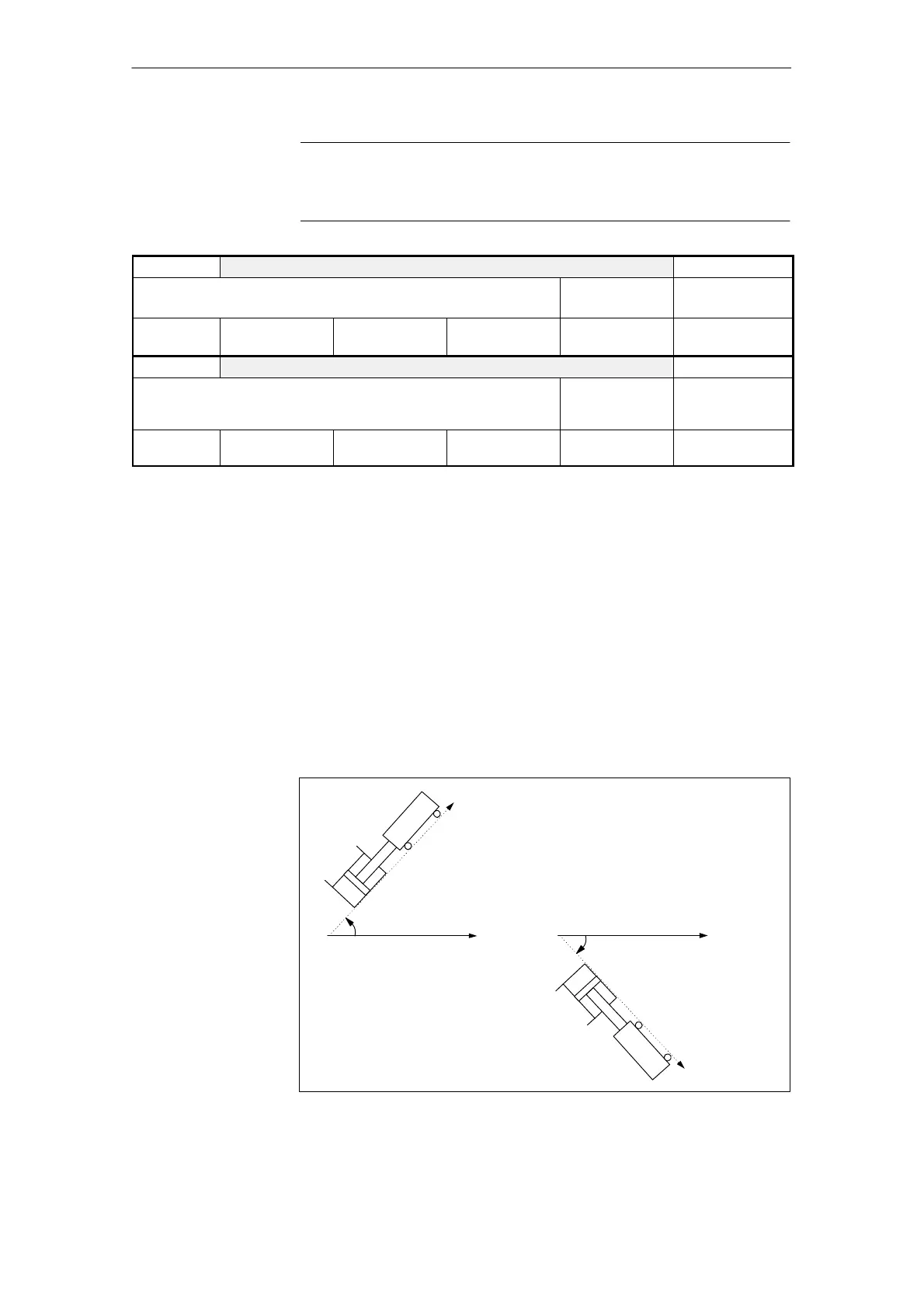
The mounting position of the cylinder (MD 5151) specifies to what degree the
force due to weight of the moved mass (MD 5150) is taken into account in cal-
culating the servo gain and maximum piston travel-in/travel-out speed.
It is assumed that the moved mass will act in the direction of the cylinder axis. If
the weight of the moved mass does not act in this direction, however, MD 5151
must be converted accordingly.
A distinction is made between two different mounting methods in the HLA:
1. The cylinder is stationary, the moved mass is attached to the piston rod (MD
5152 bit 0=0).
2. The piston is stationary, the moved mass is attached to the cylinder (MD
5152 bit 0=1).
The Calculate drive model data routine calculates the weight force applied to
the cylinder from MD 5150...MD 5152 and enters the result in MD 5231.
O
B
MD 5150
Positive sign in
MD5151
O
B
MD 5150
Negative sign in
MD5151
Fig. 4-17 Mounting position of drive referred to A end
4 Firmware Drive Functions
02.99

 Loading...


