EasyManuals Logo

Siemens Sinumerik 840D Series Function Manual

Siemens Sinumerik 840D Series
288 pages
To Next Page IconTo Next Page
To Previous Page IconTo Previous Page
Page #26 background imageLoading...
Page #26 background image
10.03
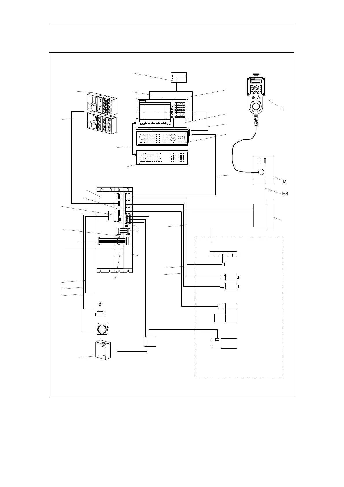
2.2 Integration in SINUMERIK 840D/SIMODRIVE 611 digital
2-26
Siemens AG, 2003. All rights reserved
SINUMERIK 840D/SIMODRIVE 611 digital, HLA Module (FBHLA) - 10.03 Edition
MCP
Floppy
MMC CPU
Device bus
Battery and plug-in fan
unit
HLA
module
NCU
Digital I/O
(high-speed NC I/O)
Handwheel
(2x) (1x of M)
Measure-
ment (2x)
S7-300
J
A
G3
B
F
G2
G1
G4
D
I
C
H1
H9
H4
H5
H6
B1
K
ÄÄ
ÄÄ
M
H8
L
N
H3
H2
External 26.5 V
supply
Enable
BERO
inputs
I1
H12
H11
H10
E
SITOP power
(external PS)
P
Note:
Display of hydraulics for one axis
Servo solenoid
Pressure sensor A
Position sensing
Pressure sensor B
Shutoff valve
O
MS
valve
(GND)
Fig. 2-3 System components
2 Configuration
02.99

Table of Contents

Other manuals for Siemens Sinumerik 840D Series

Questions and Answers:

Question and Answer IconNeed help?

Do you have a question about the Siemens Sinumerik 840D Series and is the answer not in the manual?

Siemens Sinumerik 840D Series Specifications

General IconGeneral
AxesUp to 31 axes
Power Supply24 V DC
Control TypeCNC
InterfaceEthernet, PROFIBUS
DisplayTFT color display
PLCIntegrated PLC (programmable logic controller)
Operating Temperature0°C to 45°C
Relative HumidityUp to 95% (non-condensing)
Max. Number of ChannelsUp to 10 channels

Related product manuals