10.03
3.9 Fine adjustment and optimization
3-70
Siemens AG, 2003. All rights reserved
SINUMERIK 840D/SIMODRIVE 611 digital, HLA Module (FBHLA) - 10.03 Edition
3. f
valve
>> f
cylinder
(f
)
The valve can actively influence all natural frequencies of the drive.
Valve:
fv=100 Hz; Dv=0.8
Drive:
fa=20 Hz; Da=0.1
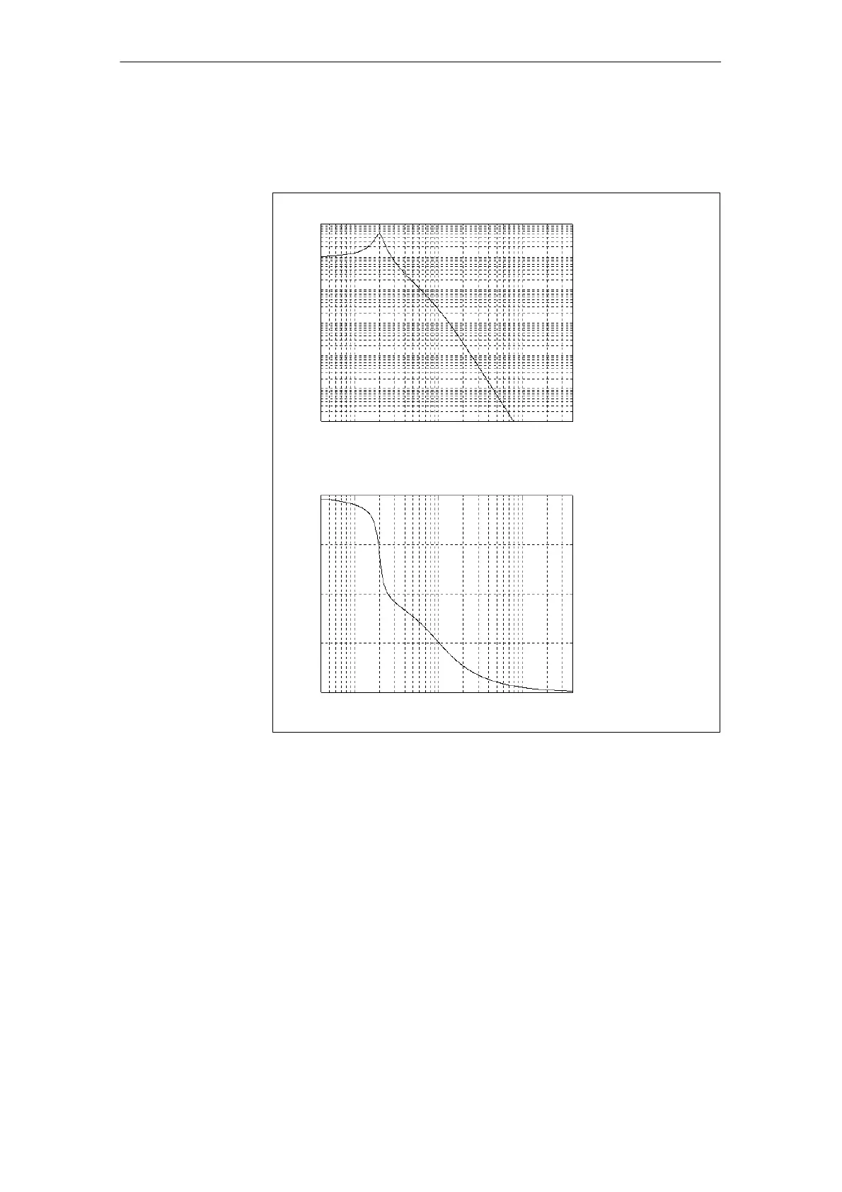
Amplitude log frequency curve
log f
log f
10
1
10
2
10
3
10
1
10
1
10
2
10
3
10
0
10
-1
10
-2
10
-3
10
-4
10
-5
-90
-180
-270
Phase angle log value
Phase frequency curve
Fig. 3-24 Frequency response of controlled system (f
valve
>> f
cylinder
)
The controller components are optimized in the following order:
1. P component (proportional component)
2. D component (derivative component)
3. I component (integral component)
The preferred method of optimization uses unit step functions (step response)
with the function generator (FG) after entering a velocity setpoint v
set
.
The measuring function with noise signals (FFT, PBRS) may be difficult to inter-
pret owing to non-linearities in the controlled system.
Differences in the characteristic data may be caused as follows:
S Theor. valve: Real valve
S Pipes: Control pressure = f(Q)
S Additional valves; shut-off valves; filters; throttles (pressure measuring
plates)
02.99
 Loading...


